Ir al contenido










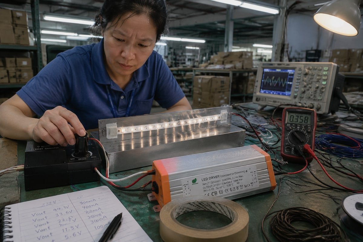
Las tiras LED parpadean con controladores TRIAC de CV más a menudo que cualquier otra queja que registramos en nuestra fábrica de controladores. Frustra a los instaladores, mata la confianza en el proyecto y detiene los pedidos repetidos.
Las tiras LED parpadean con controladores TRIAC de CV cuando el atenuador, el circuito de entrada del controlador y la carga LED no están correctamente emparejados. El TRIAC corta la forma de onda de CA, y un controlador incompatible no logra mantener una regulación de CC estable, especialmente en niveles de atenuación bajos, cargas bajas o con un emparejamiento incorrecto de borde ascendente/descendente.
Esa respuesta suena simple. Pero los detalles importan. A continuación, desgloso las causas reales, las soluciones que funcionan y cómo calificar productos antes de comprar al por mayor.
¿Qué causa que mis tiras de LED parpadeen cuando uso controladores CV TRIAC?
El año pasado, nuestro equipo de control de calidad rastreó la queja de parpadeo de un cliente de Singapur hasta una causa raíz: el circuito de entrada 1 del controlador no podía mantener el TRIAC enclavado. Ese caso dio forma a toda esta sección.
El parpadeo ocurre cuando la forma de onda recortada por fase, el circuito de entrada del controlador, su bucle de regulación de CC y la carga LED se desincronizan. Los desencadenantes comunes incluyen caída de corriente de mantenimiento, capacitancia de entrada excesiva, desajuste de borde ascendente/descendente, ciclos de protección por hipo, y cargas por debajo del requisito de carga mínima del controlador.
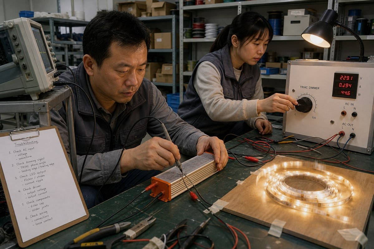
La mayoría de las personas lo enmarcan como “incompatibilidad TRIAC”. Ese marco es demasiado vago para arreglar algo. La cadena real es esta: forma de onda recortada por fase → circuito de entrada del controlador → regulación de CC y bucle de control → carga LED. El parpadeo aparece cuando cualquier eslabón de esa cadena se rompe.
La causa más pasada por alto: corriente de mantenimiento
Un TRIAC necesita suficiente corriente fluyendo a través de él para permanecer enclavado durante cada medio ciclo de CA. Un controlador con una corriente de entrada pequeña o altamente no lineal puede hacer que el TRIAC se apague temprano o se dispare de manera inconsistente. Esto empeora cerca del fondo del rango de atenuación, porque la ventana de conducción 2 ya es corta. Por eso el parpadeo a menudo aparece solo por debajo de aproximadamente 20% de brillo. El sistema funciona bien a plena potencia, luego parpadea, chasquea o brilla cuando se atenúa.
La lista completa de mecanismos de parpadeo
En nuestro laboratorio, clasificamos las quejas de parpadeo en los mecanismos a continuación. Cada uno tiene una solución diferente, así que identificar el correcto ahorra semanas.
| Mecanismo | Lo que realmente sucede | Síntoma típico |
|---|---|---|
| Caída de corriente de mantenimiento | El controlador consume muy poca corriente para mantener el TRIAC enclavado | Parpadeo o chasquidos en niveles de atenuación bajos |
| Desajuste de borde ascendente/descendente | El controlador no puede decodificar el estilo de recorte de fase del atenuador | Parpadeo en todo el rango |
| Timbre de entrada del filtro EMI | Los capacitores de entrada resuenan en cada disparo del TRIAC | Brillo o zumbido cerca del rango medio |
| Jitter de detección de cruce por cero | El controlador lee mal el tiempo de la forma de onda recortada | Parpadeo aleatorio e irregular |
| Ciclos de protección por hipo | La protección contra sobrecarga reinicia el controlador repetidamente | Parpadeo lento y rítmico de encendido-apagado |
| Patrones de batido entre ondulación y PWM | La ondulación de CA rectificada interfiere con la frecuencia de atenuación PWM interna | Efecto de desplazamiento lento o estroboscópico |
| Deriva térmica | Los umbrales de enclavamiento cambian a medida que los componentes se calientan | Parpadeo que comienza después del calentamiento |
| Contaminación armónica | Otras cargas no lineales muescan la forma de onda de CA en el circuito | Parpadeo solo cuando otros equipos funcionan |
| Caída de voltaje en tramos de CC | Cable de tamaño insuficiente o tramos largos causan oscilaciones de caída | Parpadeo en el extremo lejano de la tira |
| Desajuste de impedancia reflejada | La inductancia parásita de la tira altera el bucle de regulación de salida | Inestabilidad con tiras muy largas |
Nota que solo algunos de estos son problemas del atenuador. Varios son problemas de entrega de energía que simplemente se vuelven visibles cuando la atenuación elimina el margen del sistema.
¿Cómo puedo arreglar el parpadeo en mis proyectos de iluminación con tiras LED regulables por TRIAC?
Un cliente en Vietnam devolvió una vez tres drivers “defectuosos” a nuestro taller. Los tres pasaron nuestras pruebas de banco. Su problema real era la caída de voltaje en un tramo largo de tira en el sitio de trabajo.
Solucione el parpadeo probando en orden: omita el atenuador, verifique que el voltaje y la potencia del driver coincidan con la tira, confirme que se cumple la carga mínima del atenuador, apriete cada conexión, mida la caída de voltaje a lo largo del tramo y, finalmente, reemplace el driver con una unidad CV clasificada para corte de fase.
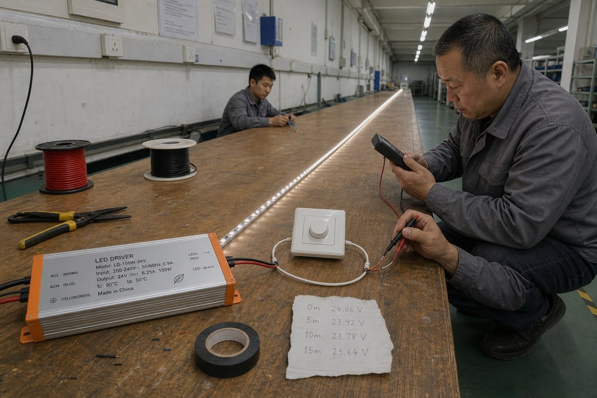
La forma más rápida de solucionar el parpadeo es dejar de adivinar y comenzar a eliminar. La distinción clave es entre parpadeo inducido por el atenuador y parpadeo por entrega de energía. Se ven idénticos a simple vista, pero requieren soluciones opuestas. Aquí está la secuencia de eliminación que recomendamos a nuestros clientes de ingeniería.
- Omita el atenuador. Conecte el driver directamente a la red eléctrica. Si el parpadeo desaparece, el problema está en la cadena de atenuación 3. Si persiste, examine la entrega de energía en su lugar.
- Verifique la coincidencia eléctrica. Confirme que el transformador LED de bajo voltaje emite los 12V o 24V correctos, y que su potencia cubre la tira con margen. Un driver funcionando al límite puede entrar en protección de interrupción, que se ve como un parpadeo rítmico.
- Verifique la carga mínima del atenuador. Muchos atenuadores de pared necesitan una potencia mínima para operar. Una tira corta a baja luminosidad puede estar por debajo de ese mínimo, por lo que el atenuador se enciende y apaga cíclicamente.
- Inspeccione cada conexión. Terminales sueltos, empalmes corroídos y conectores de clip baratos crean contacto intermitente que imita perfectamente problemas del atenuador.
- Mida el voltaje en ambos extremos de la tira. Si ve más de aproximadamente 0.5V de caída de principio a fin, la caída está contribuyendo al parpadeo. Acorte el tramo, aumente el calibre del cable o alimente desde ambos extremos.
- Cambie el driver al final. Si los pasos uno a cinco pasan y el parpadeo persiste, reemplace el driver con una unidad explícitamente clasificada para atenuación de corte de fase y confirmada contra su modelo de atenuador.
Seguir este orden es importante. En nuestros registros de posventa, una gran parte de las “fallas de driver” resultan ser problemas de cableado, dimensionamiento de carga o carga mínima del atenuador que un driver nuevo nunca habría solucionado.
¿Qué interruptores reguladores TRIAC son realmente compatibles con mis controladores LED de CV?
Elegir entre un atenuador de fase directa y un modelo de borde descendente es una compensación que nuestros ingenieros sopesan constantemente: fiabilidad de enclavamiento bruto versus rendimiento suave en el extremo bajo.
Los atenuadores TRIAC compatibles coinciden con el método de atenuación declarado del driver—borde ascendente, borde descendente o ambos—cumplen con el perfil de corriente de entrada del driver y tienen una clasificación de carga mínima que la tira conectada puede satisfacer. Siempre confirme el emparejamiento contra la lista de compatibilidad de atenuadores probados del fabricante del driver.
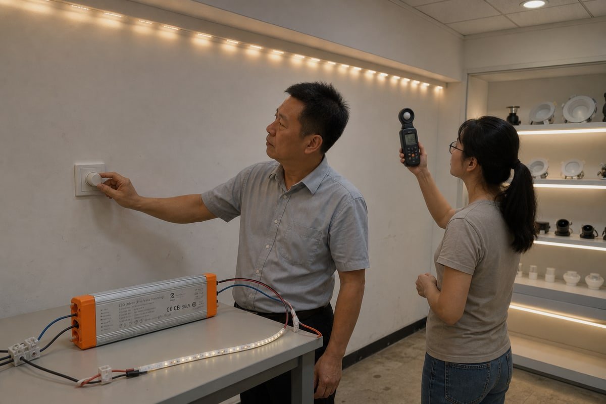
La compatibilidad del interruptor atenuador es donde la mayoría de los proyectos fallan, así que comience con la comparación de borde ascendente vs borde descendente. Las dos tecnologías cortan la forma de onda de CA de manera diferente, y un driver diseñado para una puede comportarse mal en la otra.
| Factor | Borde ascendente (fase directa) | Borde descendente (tipo ELV) |
|---|---|---|
| Cómo corta la forma de onda | Corta el frente de cada medio ciclo | Corta la parte trasera de cada medio ciclo |
| Objetivo de diseño original | Cargas incandescentes y magnéticas | Cargas electrónicas de bajo voltaje |
| Sensibilidad a la corriente de mantenimiento | Alta—necesita corriente constante para mantenerse enclavado | Baja—usa transistores, no un TRIAC de enclavamiento |
| Requisito de carga mínima | A menudo 25W o más | Normalmente, mucho más bajo |
| Comportamiento de atenuación en el extremo bajo | Propenso a caídas y destellos | Típicamente más suave y silencioso |
| Mejor emparejamiento | Drivers explícitamente clasificados para borde ascendente | Diseños de driver atenuables ELV |
Ahora déjeme abordar una objeción común de los compradores. Algunos ingenieros me dicen que la atenuación TRIAC es inherentemente incorrecta para tiras LED, y que solo una solución MOSFET o de borde descendente puede estar libre de parpadeo. Entiendo de dónde viene esa visión—los atenuadores incandescentes heredados en unidades genéricas de fuente de alimentación de voltaje constante 4 parpadean mal. Pero la conclusión está desactualizada. Un driver cuya etapa de entrada está diseñada para decodificar la entrada de corte de fase, presentar una corriente estable al TRIAC y regular limpiamente en niveles de atenuación profunda puede funcionar muy bien en hardware de borde ascendente 5. El espectro real va desde “configuraciones genéricas antiguas que parpadean” hasta “sistemas compatibles con TRIAC diseñados que no lo hacen”.”
La regla práctica que damos a los distribuidores: nunca califiques un atenuador solo. Califica el atenuador, el controlador y la tira como un solo sistema, y pregunta a tu proveedor por su lista de compatibilidad probada antes de especificar cualquier cosa.
¿Cómo elijo un driver TRIAC de CV confiable para prevenir el parpadeo en pedidos al por mayor?
Una lección de años exportando controladores a Europa y el Sudeste Asiático destaca para mí: una línea de hoja de datos que dice 24V de voltaje constante no te dice nada sobre la atenuación.
Elige un controlador etiquetado explícitamente como 24V de voltaje constante, atenuable por TRIAC/corte de fase—no meramente de voltaje constante. Verifica el soporte de borde delantero y trasero, la carga mínima y máxima, la estabilidad de atenuación en el extremo bajo, el comportamiento de la corriente de entrada, marcas de seguridad como CE, CB y SELV, y luego prueba con muestras la combinación completa de atenuador-controlador-tira antes de comprometerte.
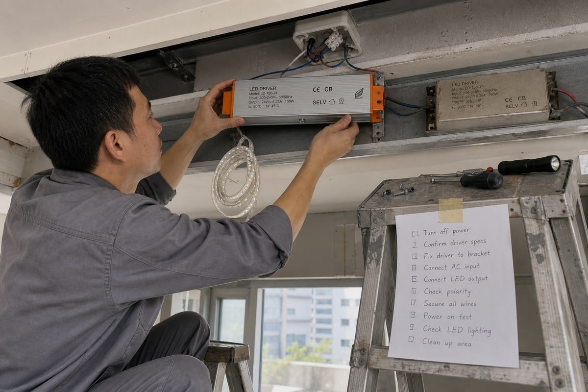
Aquí está el problema oculto que más dinero cuesta a los compradores. Una tira LED de 24V puede ser perfectamente compatible eléctricamente con un controlador CV de 24V y aún así parpadear al atenuarse. La compatibilidad de voltaje y la compatibilidad de atenuación son dos cosas diferentes. Un suministro de energía de voltaje constante convencional puede producir excelente CC de 24V en operación normal, pero su circuito de entrada puede ser completamente inadecuado para una forma de onda de corte de fase. Conectarlo detrás de un atenuador TRIAC no lo convierte mágicamente en un controlador atenuable por TRIAC. La especificación debe decir algo como “24V de voltaje constante, atenuable por TRIAC/corte de fase”—no simplemente “suministro de energía de voltaje constante de 24V”.”
Las seis preguntas que debes hacer a cada proveedor
Antes de cualquier pedido al por mayor, decimos a los compradores que vayan más allá de “¿es atenuable por TRIAC?” y hagan estas seis preguntas en su lugar:
- ¿Está diseñado para borde delantero, borde trasero o ambos?
- ¿Cuál es la carga mínima y máxima del controlador?
- ¿Cuál es la forma de onda de la corriente de entrada del controlador?
- ¿Mantiene una regulación estable en tu nivel mínimo de atenuación previsto?
- ¿La tira LED está realmente consumiendo suficiente energía para el rango de operación del controlador?
- ¿El atenuador tiene un requisito de carga mínima propio?
La lista de verificación de calificación para pedidos al por mayor
| Punto de Verificación | Qué hay que comprobar | Señal de alerta |
|---|---|---|
| Etiqueta de atenuación | Indica atenuable por TRIAC/corte de fase explícitamente | Solo dice voltaje constante |
| Marcas de seguridad | CE, CB y SELV impresos en la carcasa | Certificados faltantes o no verificables |
| Diseño térmico | Carcasa de aluminio con ranuras de disipación de calor | Plástico sellado sin vía térmica |
| Afirmaciones de sin parpadeo | Pregunta si la atenuación de 0–100% se aplica a tu atenuador y carga | Afirmación dada sin lista de atenuadores probados |
| Prueba de extremo bajo | Muestra probada a tu luminosidad mínima real | Solo probada a salida completa |
| Términos de garantía | Garantía por escrito que cubre fallas de atenuación | Garantía excluye el comportamiento de atenuación |
En el lado del hardware, la calidad de construcción física te dice mucho. Nuestras propias unidades usan una carcasa de aluminio cepillado con ranuras de disipación de calor acanaladas, porque la deriva térmica en un controlador caliente puede cambiar el comportamiento de enganche y crear parpadeo que solo aparece después del calentamiento. También trata el marketing de “0–100% sin parpadeo” como una afirmación de compatibilidad, no una garantía universal—solo se cumple con atenuadores probados en el rango de carga declarado. Mi conclusión B2B más fuerte: no califiques un controlador CV como atenuable por TRIAC solo porque acepta un atenuador TRIAC. La prueba real es si la combinación completa de atenuador, controlador y tira LED permanece estable en todo tu rango de atenuación requerido.
Conclusión
El parpadeo es un desajuste del sistema, no un misterio. Iguala el atenuador, el controlador y la tira; prueba la cadena completa; y solo compra a proveedores que califiquen combinaciones completas.
Notas al pie
- Explica la función de la etapa de entrada en el control de potencia basado en TRIAC. ↩︎
- Explicación técnica del control por disparo de fase y el tiempo de conducción. ↩︎
- La URL original del Departamento de Energía está en 404; esta es la página autorizada actualizada que explica los fundamentos del parpadeo LED y los componentes del sistema. ↩︎
- Normas de la Directiva de Baja Tensión de la UE para equipos eléctricos de voltaje constante. ↩︎
- Norma NEMA sobre compatibilidad de atenuación para iluminación de estado sólido. ↩︎