Skip to content










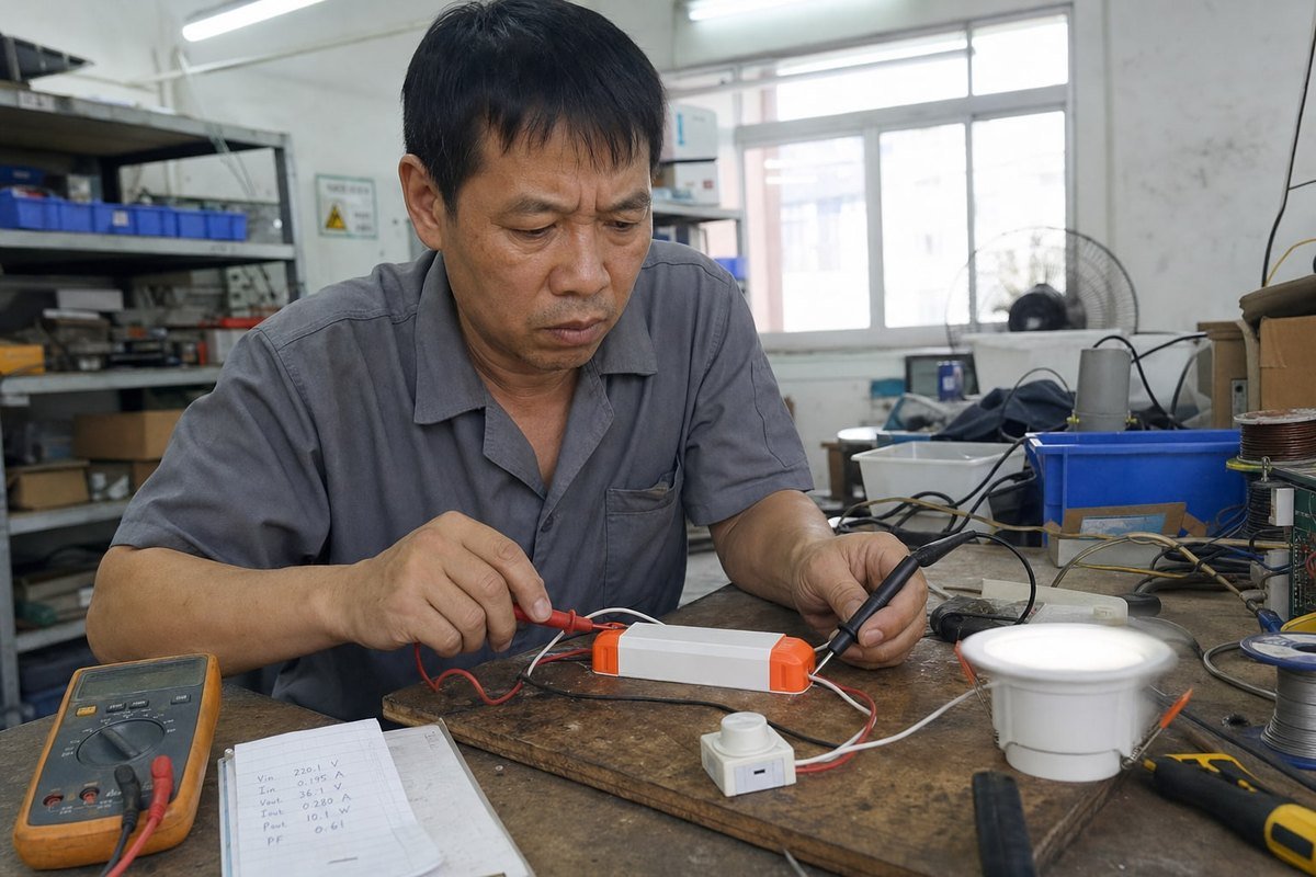
ข้อร้องเรียนเรื่องการกะพริบสามารถทำให้โปรเจกต์ไฟพังได้อย่างรวดเร็ว ไฟ LED ที่กะพริบร่วมกับไดรเวอร์ CC TRIAC เป็นเหตุผลในการคืนสินค้าที่เราตรวจสอบบ่อยที่สุด สิ่งที่น่าหงุดหงิดคือ? ไดรเวอร์มักทดสอบผ่านบนโต๊ะของเรา แต่กลับกะพริบอย่างรุนแรงกับดิมเมอร์ของลูกค้า ความไม่ตรงกันนั้นคือสิ่งที่ฉันต้องการอธิบายให้ชัดเจนที่นี่ เพื่อให้คุณหยุดปัญหาก่อนที่มันจะถึงมือลูกค้าของคุณ.
ไฟ LED กะพริบร่วมกับไดรเวอร์ CC TRIAC เพราะดิมเมอร์แบบ phase-cut ถูกออกแบบมาสำหรับโหลดแบบ resistive ของหลอดไส้ กระแส LED ที่ต่ำตกต่ำกว่ากระแส holding ของ TRIAC ตัวเก็บประจุอินพุตชาร์จเป็นจังหวะ และการสั่นของฟิลเตอร์ EMI รบกวนการยิงซ้ำ—ทำให้ TRIAC ปลดล็อกและไดรเวอร์รีสตาร์ทอย่างเห็นได้ชัด.
นั่นคือคำตอบสั้นๆ แต่ถ้าคุณซื้อหรือออกแบบไดรเวอร์ LED เพื่อการทำงาน คุณต้องการมากกว่าบทสรุป ให้ฉันพาคุณผ่านสาเหตุ วิธีแก้ไข และการทดสอบที่เราทำก่อนที่ไดรเวอร์ใดๆ จะออกจากโรงงานของเรา.
อะไรทำให้เกิดการกะพริบเมื่อฉันจับคู่ไดรเวอร์ CC กับดิมเมอร์ TRIAC?
ไม่กี่ปีที่ผ่านมา ผู้ซื้อชาวฝรั่งเศสคนหนึ่งของเราส่งวิดีโอไฟดาวน์ไลต์ที่กะพริบที่ความสว่าง 20% ให้ฉัน ฟิกซ์เจอร์ปกติดี ไดรเวอร์ปกติดี ปัญหาคือการจับคู่ และเรื่องนั้นเกิดขึ้นซ้ำทุกสัปดาห์ในกล่องจดหมายสนับสนุนของเรา.
การกะพริบเกิดขึ้นเพราะดิมเมอร์ TRIAC ต้องการกระแส latching และ holding อย่างต่อเนื่องเพื่อให้ยังนำไฟฟ้า ในขณะที่ไดรเวอร์กระแสคงที่ดึงกระแสแบบพัลส์และ capacitive เมื่อการดึงของไดรเวอร์ต่ำกว่าเกณฑ์ holding TRIAC จะปลดล็อกกลางรอบ ไดรเวอร์สูญเสียพลังงาน รีสตาร์ท และ LED กะพริบอย่างเห็นได้ชัด.
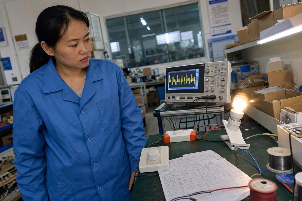
รากของปัญหาคือความล้มเหลวในการสื่อสารระหว่างอุปกรณ์สองตัวที่สร้างบนสมมติฐานที่ต่างกัน ดิมเมอร์ TRIAC ทำการลดแสงแบบ phase-cut: มันตัดส่วนหนึ่งของแต่ละครึ่งรอบ AC และส่งส่วนที่เหลือให้โหลด ไส้หลอดแบบ resistive บริสุทธิ์ ดังนั้นมันจึงดึงกระแสเรียบในทันทีที่ TRIAC ยิง TRIAC ล็อก อยู่เหนือ กระแส holding 1, และทุกอย่างทำงานได้.
ไดรเวอร์ LED กระแสคงที่ทำงานไม่เหมือนไส้หลอดเลย มันแปลงกระแส AC ที่ถูกตัด ชาร์จ ตัวเก็บประจุอินพุต 2 เป็นจังหวะแหลมคม แล้วควบคุมกระแสคงที่ให้กับสาย LED ระหว่างจังหวะการชาร์จเหล่านั้น กระแสที่ดิมเมอร์เห็นสามารถยุบลงจนแทบไม่มีอะไร.
กลไกการกะพริบทีละขั้นตอน
- ดิมเมอร์ตัดรูปคลื่นและยิง TRIAC.
- ตัวเก็บประจุอินพุตของไดรเวอร์ดึงกระแสพุ่งแหลม.
- กระแสจากนั้นตกลงต่ำกว่ากระแส holding ของ TRIAC.
- TRIAC ปลดล็อกเร็วหรือยิงซ้ำอย่างไม่สม่ำเสมอภายในครึ่งรอบเดียวกัน.
- แหล่งจ่ายภายในของไดรเวอร์ทรุด ตัวควบคุม IC รีเซ็ต และกระแสเอาต์พุตลดลง.
- LED กะพริบหรือเต้นเป็นจังหวะ—มักเป็นเอฟเฟกต์สโตรโบสโคปิกที่มองเห็นได้.
ปัจจัยรองที่เราเห็นในห้องแล็บ
นอกเหนือจากความไม่ตรงกันของกระแส holding หลัก วิศวกรของเราตรวจพบการกะพริบจากสาเหตุรองเหล่านี้เป็นประจำ:
| สาเหตุ | สิ่งที่เกิดขึ้น | จุดที่แสดงออก |
|---|---|---|
| การสั่นของฟิลเตอร์ EMI | การเพิ่มขึ้นของแรงดัน TRIAC ที่ชันกระตุ้นฟิลเตอร์อินพุต; การสั่นทำให้การตรวจจับการลดแสงผิดพลาด | การกะพริบแบบสุ่มที่ระดับลดแสงกลาง |
| วงจร bleeder อ่อนแอ | กระแสที่ดึงไม่เพียงพอในช่วง off-time เพื่อให้ TRIAC ล็อกอยู่ | การกะพริบที่ระดับลดแสงต่ำ |
| การขาดพลังงานของตัวควบคุม IC | มุมนำไฟฟ้าสั้นทำให้แหล่งจ่าย IC ขาด; ไดรเวอร์เข้าสู่โหมด hiccup | การกะพริบใกล้ความสว่างต่ำสุด |
| ค่าออฟเซ็ต DC ของไฟเมนส์ | การยิงไม่สมมาตรระหว่างครึ่งรอบ | การมอดูเลต 50/60 Hz ที่มองเห็นได้ |
| สายเอาต์พุตยาว | ความจุปรสิตทำให้วงจรกระแสไม่เสถียรที่รอบการทำงานต่ำ | การสั่นไหวระหว่างการลดแสงลึก |
ไดรเวอร์กระแสคงที่แบบ TRIAC dimmable ที่ทันสมัย—รวมถึงหน่วยขนาดกะทัดรัดที่เราสร้าง—จัดการปัญหาเหล่านี้ด้วยวงจร bleeder แบบแอคทีฟ ฟิลเตอร์ EMI แบบหน่วง 3, และลอจิกตรวจจับเฟสที่ปรับสำหรับรูปคลื่นที่ถูกตัด แต่แม้แต่ไดรเวอร์ที่ดีที่สุดก็ไม่สามารถแก้ดิมเมอร์ทุกตัวได้ ซึ่งนำเรามาสู่ความเข้ากันได้.
ฉันจะเลือกไดม์เมอร์ TRIAC ที่เข้ากันได้เพื่อหลีกเลี่ยงการกะพริบในการออกแบบไดรเวอร์ LED แบบ CC ของฉันได้อย่างไร?
คำถามเรื่องความเข้ากันได้ครอบงำการโทรทางเทคนิคที่ฉันรับกับผู้ซื้อ เมื่อเราส่งไดรเวอร์ไปยุโรป เรามักถามเสมอว่าโปรเจกต์ระบุยี่ห้อดิมเมอร์ใด—เพราะความเข้ากันได้ของสวิตช์ดิมเมอร์ตัดสินความสำเร็จมากกว่าสเปกไดรเวอร์ใดๆ เพียงอย่างเดียว.
เลือกดิมเมอร์จากรายการความเข้ากันได้ที่ทดสอบแล้วของผู้ผลิตไดรเวอร์ จับคู่โทโพโลยี leading edge เทียบกับ trailing edge กับการออกแบบไดรเวอร์ ตรวจสอบว่าดิมเมอร์ได้รับการจัดอันดับสำหรับโหลด LED และยืนยันว่ากำลังไฟ LED ที่เชื่อมต่ออยู่ในช่วงโหลดต่ำสุดและสูงสุดของดิมเมอร์อย่างสบายๆ.

ไม่ใช่ว่าดิมเมอร์แบบตัดเฟสทุกตัวจะทำงานเหมือนกัน และสิ่งที่คุณต้องเข้าใจก่อนคือความแตกต่างระหว่าง leading edge และ trailing edge.
Forward phase เทียบกับ reverse phase: ทำความเข้าใจโทโพโลยีของคุณ
ดิมเมอร์แบบ forward phase (leading-edge, อิงตาม TRIAC) ตัดจุดเริ่มต้นของแต่ละครึ่งรอบ แรงดันไฟฟ้าจะพุ่งขึ้นอย่างฉับพลัน ซึ่งก่อให้เกิด กระแสพุ่งสูง (inrush spikes) 4 และอาจกระตุ้นการสั่นพ้องของตัวกรอง EMI ดิมเมอร์แบบ reverse phase (trailing-edge, อิงตาม MOSFET) ตัดจุดสิ้นสุดของครึ่งรอบ แรงดันไฟฟ้าจะเพิ่มขึ้นอย่างนุ่มนวล ซึ่งเป็นมิตรกับอินพุตของไดรเวอร์แบบ capacitive มากกว่า—แต่ไดรเวอร์ที่ปรับจูนสำหรับการตรวจจับแบบ forward phase อาจอ่านสัญญาณ reverse phase ผิดไปโดยสิ้นเชิง.
| คุณสมบัติ | Forward Phase (Leading Edge) | Reverse Phase (Trailing Edge) |
|---|---|---|
| อุปกรณ์สวิตช์ | ไตรแอก | MOSFET/IGBT |
| การเพิ่มขึ้นของแรงดันไฟฟ้า | ฉับพลัน, dV/dt สูงชัน | ค่อยเป็นค่อยไป, นุ่มนวล |
| ต้องมีกระแสคงค้าง (holding current) | ใช่, สำคัญมาก | ไม่ |
| ข้อกำหนดโหลดขั้นต่ำ | มัก 25–60W | โดยปกติต่ำกว่ามาก |
| เหมาะที่สุดกับ | ไดรเวอร์ที่มีวงจร bleeder แข็งแรง | อินพุตไดรเวอร์ LED แบบ capacitive |
| รูปแบบความล้มเหลวทั่วไป | กระพริบ, ดับที่ระดับความสว่างต่ำ | ตรวจจับผิดหากไดรเวอร์คาดหวัง leading edge |
รายการตรวจสอบการเลือกใช้งานเชิงปฏิบัติ
จากประสบการณ์การส่งออกของเรา นี่คือลำดับขั้นที่ฉันแนะนำให้ผู้ซื้ออย่างคุณ:
- เริ่มจากรายการความเข้ากันได้. เราทดสอบไดรเวอร์ของเรากับรุ่นดิมเมอร์ยอดนิยมและเผยแพร่ผลลัพธ์ คู่ที่ผ่านการทดสอบช่วยลดการคาดเดาส่วนใหญ่ได้.
- ตรวจสอบพิกัด LED ของดิมเมอร์. ดิมเมอร์หลอดไส้รุ่นเก่ามักระบุความต้องการโหลดขั้นต่ำ 25W–60W หลอด LED 8W สามดวงอาจไม่เป็นไปตามข้อกำหนดนั้น.
- ลดพิกัดดิมเมอร์สำหรับโหลด LED. ดิมเมอร์หลอดไส้ 400W มักรองรับได้เพียงประมาณ 10% ของกำลังไฟนั้นในหน่วยวัตต์ LED เนื่องจากกระแสพุ่งสูง.
- จับคู่โทโพโลยี. ยืนยันว่าไดรเวอร์ของคุณคาดหวังสัญญาณ forward phase หรือ สัญญาณ reverse phase 5 ก่อนกำหนดสเปกสวิตช์ติดผนัง.
- สอบถามเกี่ยวกับเส้นโค้งการหรี่แสง. ไดรเวอร์และดิมเมอร์ที่มีเส้นโค้งไม่ตรงกันอาจไม่กระพริบ แต่จะหรี่แสงได้ไม่ดี—ช่วงไร้การตอบสนองที่ด้านบน และการตัดไฟกะทันหันที่ด้านล่าง.
เคล็ดลับอีกข้อจากโรงงานของเรา: หากโปรเจกต์ผสมประเภทโคมไฟบนวงจรดิมเมอร์เดียว ให้ทดสอบโหลดแบบผสมทั้งหมด ไม่ใช่ทีละดวง ปฏิสัมพันธ์ระหว่างไดรเวอร์บนสายตัดเฟสเดียวกันทำให้เกิดการกระพริบที่การทดสอบแบบเดี่ยวไม่เคยเผยให้เห็น.

ควรตรวจสอบปัญหาโหลดขั้นต่ำหรือกระแสคงค้างใดบ้างเพื่อป้องกันการกะพริบ?
มีการแลกเปลี่ยนที่เราชั่งน้ำหนักในการออกแบบไดรเวอร์ทุกครั้ง: ต้องสิ้นเปลืองกระแส bleeder เท่าใด น้อยเกินไป TRIAC จะดับที่ระดับความสว่างต่ำ มากเกินไป ประสิทธิภาพจะลดลงและไดรเวอร์จะร้อน การหาสมดุลนี้ให้ถูกต้องคือจุดที่การออกแบบไดรเวอร์ TRIAC แบบ CC ยากอย่างแท้จริง.
ตรวจสอบว่าโหลด LED ทั้งหมดเป็นไปตามข้อกำหนดโหลดขั้นต่ำของดิมเมอร์ กระแสอินพุตของไดรเวอร์ยังคงสูงกว่ากระแสคงค้างของ TRIAC ทุกมุมการนำไฟฟ้า และวงจร bleeder รักษากระแสล็อค (latching current) ในช่วงมิลลิวินาทีวิกฤตหลัง TRIAC ทำงาน.
เกณฑ์กระแสสองแบบที่เกี่ยวข้องแต่แตกต่างกันควบคุมพฤติกรรมของ TRIAC และการสับสนระหว่างทั้งสองทำให้เกิดข้อผิดพลาดในการออกแบบ.
Latching current เทียบกับ holding current
Latching current คือสิ่งที่ TRIAC ต้องการทันทีหลังการกระตุ้นเพื่อให้คงสถานะเปิดเมื่อพัลส์เกตสิ้นสุดลง Holding current คือค่าที่น้อยกว่าที่ต้องการตลอดช่วงการนำไฟฟ้าเพื่อให้คงสถานะเปิด สเปก latching และ holding current แตกต่างกันตาม รุ่น TRIAC 6, แต่ค่าทั่วไปอยู่ระหว่างไม่กี่มิลลิแอมป์ถึงมากกว่า 50 mA หลอดไส้ทะลุผ่านทั้งสองค่าได้ทันที ไดรเวอร์ LED ที่หรี่แสงอาจล้มเหลวในค่าใดค่าหนึ่ง—ความล้มเหลวของ latching ทำให้เกิดการจุดพลาดทันทีหลังการกระตุ้น ในขณะที่ความล้มเหลวของ holding ทำให้เกิดการดับก่อนกำหนดในช่วงท้ายของครึ่งรอบ.
คณิตศาสตร์ที่สำคัญที่ระดับความสว่างต่ำ
การกระพริบแย่ลงเมื่อหรี่แสงลึกด้วยเหตุผลด้านพลังงานง่ายๆ ที่มุมการนำไฟฟ้าสั้น ไดรเวอร์ได้รับเพียงเสี้ยวบางๆ ของแต่ละครึ่งรอบ พลังงานต่อรอบน้อยลงหมายถึงกระแสอินพุตเฉลี่ยต่ำลง ซึ่งเป็นจุดที่ TRIAC มีแนวโน้มสูญเสียกระแสคงค้างมากที่สุด นี่คือเหตุผลที่อาการเด่นของการไม่เข้ากันคือความไม่เสถียรต่ำกว่าความสว่างประมาณ 20% ในขณะที่ความสว่างเต็มดูสมบูรณ์แบบ.
| รายการตรวจสอบ | สิ่งที่ต้องตรวจสอบ | สัญญาณเตือน |
|---|---|---|
| โหลดขั้นต่ำของตัวหรี่ไฟ | วัตต์ LED ทั้งหมดเทียบกับสเปกดิมเมอร์ | โหลดต่ำกว่าค่าต่ำสุดที่ระบุ |
| กระแสคงตัวของ TRIAC | กระแสอินพุตของไดรเวอร์ที่ระดับหรี่ต่ำสุด | กระแสลดลงต่ำกว่า ~10–50 mA |
| ประเภทวงจรเบลเดอร์ | แอคทีฟ (สวิตช์) เทียบกับพาสซีฟ (ตัวต้านทาน) | สเปกเบลเดอร์พาสซีฟพร้อมการหรี่แบบลึก |
| พฤติกรรมทางความร้อน | จังหวะเวลาของเบลเดอร์ที่อุณหภูมิใช้งาน | การกะพริบที่ปรากฏเฉพาะหลังการอุ่นเครื่อง |
| เส้นทางกระแสรั่วไหล | ไดรเวอร์รีสตาร์ทเป็นรอบเมื่อหรี่ที่ระดับต่ำสุด | การกะพริบเปิด-ปิดอย่างช้าๆ เมื่อเกือบดับ |
ทำไมเบลเดอร์แบบแอคทีฟจึงเปลี่ยนเกม
การออกแบบรุ่นเก่าใช้เบลเดอร์แบบตัวต้านทานคงที่ซึ่งสิ้นเปลืองพลังงานในทุกระดับการหรี่ การออกแบบปัจจุบันของเราใช้วงจรเบลเดอร์แบบแอคทีฟที่ดึงกระแสเสริมเฉพาะในช่วงที่เสี่ยงหลังการทริกเกอร์ TRIAC และที่มุมนำไฟฟ้าต่ำ บทเรียนหนึ่งที่เราเรียนรู้ด้วยความยากลำบาก: จังหวะเวลาของเบลเดอร์คลาดเคลื่อนตามอุณหภูมิ ไดรเวอร์ที่ผ่านการทดสอบบนแท่นทดสอบเย็นอาจกะพริบหลังจากผ่านไปสามสิบนาทีภายในโคมไฟเพดานที่อุ่น ตอนนี้เราทดสอบแบบ soak-test ไดรเวอร์ที่อุณหภูมิสูงก่อนอนุมัติการออกแบบการหรี่ใดๆ เพราะการคลาดเคลื่อนทางความร้อนในเบลเดอร์เป็นหนึ่งในแหล่งกำเนิดการกะพริบที่หลบซ่อนที่สุดในภาคสนาม.
ฉันจะทดสอบและแก้ไขปัญหาการกะพริบก่อนการผลิตจำนวนมากได้อย่างไร?
ผู้ซื้อคนหนึ่งเคยถามผมว่าทำไมเราจึงยืนยันการทดสอบกวาดสวิตช์หรี่ทั้งช่วงเมื่อตัวอย่าง “ใช้งานได้แล้ว” ในออฟฟิศของเขา สองเดือนต่อมา ล็อตการผลิตของเขาพบสวิตช์หรี่ยี่ห้ออื่นในหน้างาน—และข้อมูลการกวาดทดสอบของเราก็ช่วยโครงการไว้ได้ การทดสอบก่อนการผลิตจำนวนมากคือประกันราคาถูก.
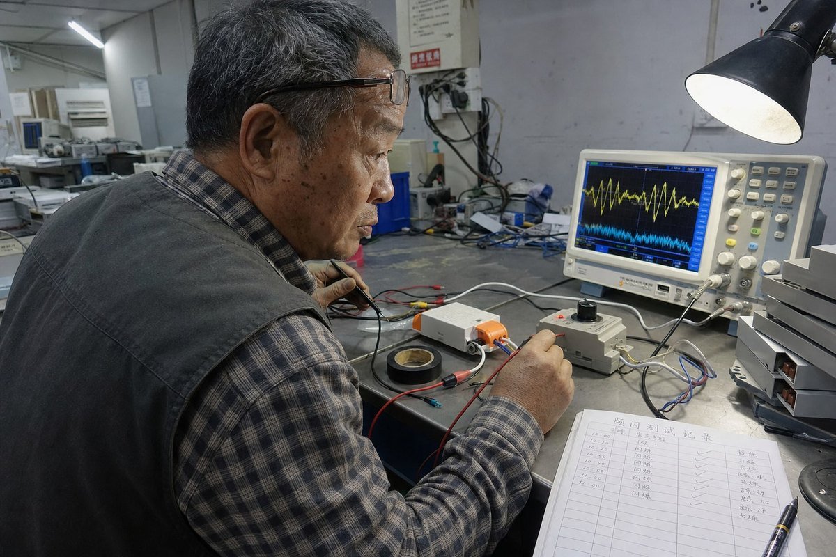
ทดสอบคู่ไดรเวอร์-ดิมเมอร์แต่ละคู่ตลอดช่วงการปรับแสงเต็มรูปแบบด้วยออสซิลโลสโคปบนกระแสอินพุตและมิเตอร์วัดการกะพริบบนเอาต์พุตแสง ตรวจสอบการล็อกที่เสถียรที่ระดับแสงต่ำสุด ตรวจสอบพฤติกรรมระหว่างการอุ่นเครื่อง ปัดกวาดดิมเมอร์หลายยี่ห้อ และยืนยันว่าไม่มีการรีสตาร์ทแบบสะดุดที่มุมการนำไฟฟ้าใดๆ.

ให้ผมแบ่งปันขั้นตอนการทำงานที่เราทำในห้อง QC ซึ่งปรับให้คุณนำไปใช้ก่อนอนุมัติล็อตการผลิตได้.
โปรโตคอลการทดสอบก่อนการผลิตเจ็ดขั้นตอน
- ทดสอบคู่ที่ตรงกันจริงบนแท่นทดสอบ. ทดสอบรุ่นสวิตช์หรี่ รุ่นไดรเวอร์ และโหลด LED ที่โครงการจะใช้จริง การใช้อะไหล่แทนจะซ่อนปัญหาไว้.
- กวาดช่วงการหรี่ทั้งหมดอย่างช้าๆ. เลื่อนจาก 100% ลงไปต่ำสุดภายใน 30 วินาที สังเกตอาการริบหรี่ กะพริบ หรือช่วงดับ—โดยเฉพาะในหนึ่งในสี่ช่วงล่างของการเดินทาง.
- วัดรูปคลื่นกระแสอินพุตด้วยออสซิลโลสโคป. ต่อ หัววัดกระแส 7 เข้ากับอินพุต AC มองหาการดรอปเอาต์ของ TRIAC แต่เนิ่นๆ (กระแสยุบกลางครึ่งรอบ) และการทริกเกอร์ซ้ำที่เกิดจากริงกิ้งของการกรอง EMI.
- วัดการกะพริบของแสงโดยตรง. ใช้มิเตอร์วัดการกะพริบหรือกล้องความเร็วเฟรมสูงเพื่อหาปริมาณเปอร์เซ็นต์การกะพริบและ ดัชนีการกะพริบ 8 ที่ระดับการหรี่หลายระดับ เอฟเฟกต์สโตรโบสโคปิกอาจมองไม่เห็นด้วยตาเปล่าแต่ชัดเจนต่อกล้องหรือผู้อยู่อาศัยที่ไวต่อแสง.
- ทดสอบ soak ทางความร้อน. ใช้งานที่การหรี่ต่ำสุดภายในตู้ที่อุณหภูมิแวดล้อมสมจริงอย่างน้อยหนึ่งชั่วโมง ตรวจสอบความเสถียรเมื่ออุ่นแล้วอีกครั้ง.
- ทดสอบจำนวนโคมไฟต่ำสุดและสูงสุด. ไดรเวอร์หนึ่งตัวบนสวิตช์หรี่ทำงานต่างจากสิบคู่ ทดสอบทั้งสองสุดของวงจรที่วางแผนไว้.
- ตรวจสอบสถานะปิด. เมื่อสวิตช์หรี่ปิดสนิท ยืนยันว่า LED ยังมืดอยู่ อาการภาพผีหรือกะพริบเป็นระยะบ่งชี้ว่ากระแสรั่วไหลค่อยๆ ชาร์จตัวเก็บประจุของไดรเวอร์และกระตุ้นการรีสตาร์ทเป็นรอบ.
การอ่านอาการ
ลายเซ็นการกะพริบที่ต่างกันบ่งชี้สาเหตุที่ต่างกัน การกะพริบเฉพาะใกล้ความสว่างต่ำสุดมักหมายถึงกระแสคงตัวหรือช่วงการหรี่ไม่เข้าคู่—ไม่ใช่ปัญหาสายไฟ การกะพริบทุกระดับบ่งชี้โทโพโลยีไม่เข้าคู่หรือการแกว่งของฟิลเตอร์ การกะพริบขณะสวิตช์หรี่ปิดหมายถึงการรั่วไหล การกะพริบหลังอุ่นเครื่องบ่งชี้การคลาดเคลื่อนทางความร้อน และอย่าลืมมุมมองสมดุล: การกะพริบในสนามบางส่วนสืบย้อนไปถึงความผันผวนของแรงดัน สายนิวทรัลหลวม หรือวงจรร่วมกับเบรกเกอร์ AFCI/GFCI ที่ตอบสนองต่อสัญญาณรบกวนฮาร์มอนิก ต้องตัดปัจจัยเหล่านั้นออกก่อนจะโทษคู่ไดรเวอร์-สวิตช์หรี่.
บทสรุป
การกะพริบกับไดรเวอร์ CC TRIAC แทบไม่ใช่ความบกพร่องของ LED มันคือความไม่เข้าคู่ของสวิตช์หรี่-ไดรเวอร์ที่คุณป้องกันได้ด้วยการจับคู่โทโพโลยี การออกแบบที่คำนึงถึงเบลเดอร์ และการทดสอบก่อนการผลิตอย่างมีวินัย หากคุณต้องการความช่วยเหลือในการจับคู่ไดรเวอร์และสวิตช์หรี่สำหรับโครงการถัดไป ทีมของเราที่ boqi ยินดีแบ่งปันข้อมูลความเข้ากันได้ของเรา.
เชิงอรรถ
- อธิบายกระแสต่ำสุดที่จำเป็นในการทำให้ TRIAC อยู่ในสถานะนำไฟฟ้า. ↩︎
- เอกสารทางเทคนิคเกี่ยวกับส่วนประกอบตัวเก็บประจุที่รับผิดชอบการดึงกระแสแบบพัลส์ในไดรเวอร์ LED. ↩︎
- บทความ Wikipedia ที่เชื่อถือได้ซึ่งอธิบายการรบกวนแม่เหล็กไฟฟ้าและเทคนิคการ suppression. ↩︎
- แหล่งข้อมูล Wikipedia ที่เชื่อถือได้ซึ่งนิยามกระแสอินรัชและผลกระทบต่อส่วนประกอบไฟฟ้า. ↩︎
- ภาพรวมทางเทคนิคของเทคโนโลยีการหรี่แบบ trailing-edge ที่ใช้กับโหลด LED แบบคาปาซิทีฟ. ↩︎
- อธิบายส่วนประกอบสารกึ่งตัวนำพื้นฐานที่ใช้ในวงจรหรี่แบบ phase-cut. ↩︎
- คู่มือจากผู้นำอุตสาหกรรมเกี่ยวกับเครื่องมือที่ใช้สำหรับวัดรูปคลื่นกระแสอินพุตในการแก้ไขปัญหา. ↩︎
- แหล่งข้อมูลภาครัฐที่กำหนดเมตริกสำหรับการวัดและหาปริมาณการกะพริบของแสงในระบบ LED. ↩︎