Aller au contenu










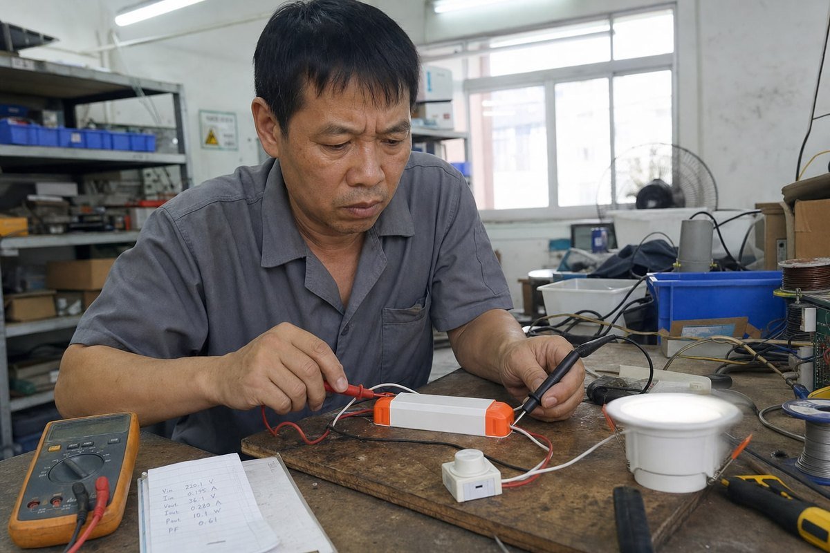
Les plaintes de scintillement peuvent couler un projet d’éclairage rapidement. Les lumières LED qui scintillent avec des drivers CC TRIAC sont la raison de retour la plus courante que nous enquêtons. La partie frustrante ? Le driver fonctionne souvent bien sur notre banc d’essai, mais scintille mal sur le gradateur du client. Ce décalage est exactement ce que je veux démêler ici, afin que vous puissiez arrêter le problème avant qu’il n’atteigne vos clients.
Les lumières LED scintillent avec des drivers CC TRIAC parce que les gradateurs à découpage de phase ont été conçus pour des charges résistives à incandescence. Le faible courant LED tombe sous le courant de maintien du TRIAC, le condensateur d’entrée se charge par rafales, et l’oscillation du filtre CEM perturbe le redéclenchement—provoquant le déverrouillage du TRIAC et le redémarrage visible du driver.
C’est la réponse courte. Mais si vous achetez ou concevez des drivers LED pour vivre, vous avez besoin de plus qu’un résumé. Laissez-moi vous guider à travers les causes, les correctifs, et les tests que nous effectuons avant que tout driver ne quitte notre usine.
Qu’est-ce qui provoque le scintillement lorsque j’associe des drivers CC avec des gradateurs TRIAC ?
Il y a quelques années, un de nos acheteurs français m’a envoyé une vidéo d’un downlight strobant à 20 % de luminosité. Le luminaire était bien. Le driver était bien. L’association était le problème, et cette histoire se répète chaque semaine dans notre boîte de réception de support.
Le scintillement se produit parce que le gradateur TRIAC a besoin d’un courant de verrouillage et de maintien continu pour rester conducteur, tandis qu’un driver à courant constant tire un courant pulsé et capacitif. Lorsque la consommation du driver descend sous le seuil de maintien, le TRIAC se déverrouille en milieu de cycle, le driver perd de la puissance, redémarre, et la LED clignote visiblement.

La racine du problème est un échec de communication entre deux dispositifs construits sur des hypothèses différentes. Un gradateur TRIAC effectue un gradateur à découpage de phase : il coupe une partie de chaque demi-cycle AC et délivre le reste à la charge. Un filament à incandescence est purement résistif, donc il tire un courant lisse au moment où le TRIAC s’active. Le TRIAC se verrouille, reste au-dessus de son courant de maintien 1, et tout fonctionne.
Un driver LED à courant constant ne se comporte pas du tout comme un filament. Il redresse le AC découpé, charge un condensateur d’entrée 2 en rafales nettes, puis régule un courant fixe vers la chaîne de LED. Entre ces rafales de charge, le courant que voit le gradateur peut s’effondrer à presque rien.
Le mécanisme de scintillement étape par étape
- Le gradateur coupe la forme d’onde et active le TRIAC.
- Le condensateur d’entrée du driver tire un pic d’appel de courant net.
- Le courant descend ensuite sous le courant de maintien du TRIAC.
- Le TRIAC se déverrouille tôt ou se redéclenche de manière erratique dans le même demi-cycle.
- La rail d’alimentation interne du driver s’affaisse, le CI de contrôle se réinitialise, et le courant de sortie chute.
- La LED clignote ou pulse—souvent comme un effet stroboscopique visible.
Facteurs secondaires que nous voyons dans le laboratoire
Au-delà du décalage de courant de maintien principal, nos ingénieurs tracent régulièrement le scintillement à ces causes secondaires :
| Cause | Ce qui se passe | Où cela se manifeste |
|---|---|---|
| Oscillation du filtre CEM | La montée de tension abrupte du TRIAC excite le filtre d’entrée ; l’oscillation déclenche mal la détection de gradation | Scintillement aléatoire à mi-gradation |
| Circuit de fuite faible | Pas assez de courant tiré pendant le temps mort pour maintenir le TRIAC verrouillé | Scintillement à bas niveaux de gradation |
| Privation de puissance du CI de contrôle | Des angles de conduction courts privent l’alimentation du CI ; le driver entre en mode hoquet | Clignotement près de la luminosité minimale |
| Décalage DC du secteur | Déclenchement asymétrique entre les demi-cycles | Modulation visible à 50/60 Hz |
| Câbles de sortie longs | La capacité parasite déstabilise la boucle de courant à faibles cycles de service | Scintillement pendant la gradation profonde |
Les Drivers à courant constant dimmables TRIAC—y compris les unités compactes que nous construisons—résolvent ces problèmes avec des circuits de fuite actifs, un filtrage CEM 3, amorti, et une logique de détection de phase réglée pour les formes d’onde découpées. Mais même le meilleur driver ne peut pas réparer chaque gradateur, ce qui nous amène à la compatibilité.
Comment puis-je choisir des gradateurs TRIAC compatibles pour éviter le scintillement dans mes conceptions de pilotes LED à courant constant ?
Les questions de compatibilité dominent les appels techniques que je prends avec les acheteurs. Lorsque nous expédions des drivers en Europe, nous demandons toujours quelles marques de gradateurs le projet spécifie—parce que la compatibilité du gradateur décide du succès plus que toute spécification de driver unique.
Choisissez des gradateurs de la liste de compatibilité testée de votre fabricant de drivers, faites correspondre la topologie de bord avant vs bord arrière à la conception du driver, vérifiez que le gradateur est évalué pour les charges LED, et confirmez que la puissance LED connectée se situe confortablement dans la fenêtre de charge minimale et maximale du gradateur.

Tous les gradateurs à découpage de phase ne se comportent pas de la même manière, et la première division que vous devez comprendre est bord avant vs bord arrière.
Phase avant vs phase inverse : connaissez votre topologie
Les gradateurs à phase avant (bord avant, basés sur TRIAC) coupent le début de chaque demi-cycle. La tension s’active brusquement, ce qui crée pics d’appel de courant 4 et peuvent exciter la résonance du filtre EMI. Les gradateurs à phase inversée (à front descendant, à base de MOSFET) coupent la fin du demi-cycle. La tension monte doucement, ce qui est plus doux pour les entrées capacitives du driver—mais un driver réglé pour la détection de phase avant peut mal interpréter un signal de phase inversée.
| Fonctionnalité | Phase avant (front montant) | Phase inversée (front descendant) |
|---|---|---|
| Dispositif de commutation | TRIAC | MOSFET/IGBT |
| Montée de tension | Brusque, dV/dt raide | Progressive, douce |
| Courant de maintien nécessaire | Oui, critique | Non |
| Exigence relative à la charge minimale | Souvent 25–60 W | Généralement beaucoup plus faible |
| Mieux associé avec | Drivers avec circuits de décharge robustes | Entrées capacitives de driver LED |
| Mode de défaillance typique | Scintillement, coupure à faible gradation | Mauvaise détection si le driver attend un front montant |
Une liste de contrôle pratique pour la sélection
D’après notre expérience à l’export, voici la séquence que je recommande aux acheteurs comme vous :
- Commencez par la liste de compatibilité. Nous testons nos drivers avec des modèles de gradateurs populaires et publions les résultats. Une paire testée élimine la plupart des incertitudes.
- Vérifiez la puissance nominale LED du gradateur. Les gradateurs à incandescence anciens indiquent souvent une charge minimale de 25 W–60 W. Trois luminaires LED de 8 W peuvent ne pas la satisfaire.
- Dératez le gradateur pour les charges LED. Un gradateur à incandescence de 400 W ne gère souvent qu’environ 10 % de cette puissance en watts LED en raison des pics d’appel de courant.
- Faites correspondre la topologie. Confirmez si votre driver attend un signal de phase avant ou de phase inversée 5 avant de spécifier le contrôle mural.
- Renseignez-vous sur la courbe de gradation. Un driver et un gradateur avec des courbes incompatibles peuvent ne pas scintiller, mais ils gradateur mal—course morte en haut, coupure soudaine en bas.
Un autre conseil de notre atelier : si un projet mélange des types de luminaires sur un même circuit de gradation, testez la charge mixte complète, pas un luminaire à la fois. Les interactions entre drivers sur la même ligne à coupure de phase provoquent des scintillements que les tests unitaires ne révèlent jamais.

Quels problèmes de charge minimale ou de courant de maintien dois-je vérifier pour éviter le scintillement ?
Il y a un compromis que nous pesons dans chaque conception de driver : combien de courant de décharge brûler. Trop peu, et le TRIAC décroche à faible gradation. Trop, et l’efficacité en souffre et le driver chauffe. Trouver cet équilibre est là où la conception de driver TRIAC CC devient vraiment difficile.
Vérifiez que la charge LED totale répond à l’exigence de charge minimale du gradateur, que le courant d’entrée du driver reste au-dessus du courant de maintien du TRIAC à tous les angles de conduction, et que le circuit de décharge maintient le courant de verrouillage pendant les millisecondes critiques après le déclenchement du TRIAC.
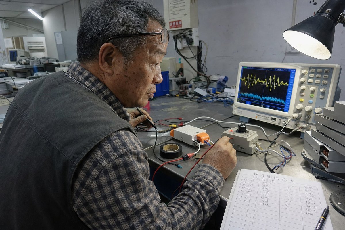
Deux seuils de courant liés mais distincts régissent le comportement du TRIAC, et les confondre provoque des erreurs de conception.
Courant de verrouillage vs courant de maintien
Le courant de verrouillage est ce dont le TRIAC a besoin immédiatement après le déclenchement pour rester allumé une fois l’impulsion de grille terminée. Le courant de maintien est la valeur plus petite dont il a besoin pendant la conduction pour rester allumé. Les spécifications de courant de verrouillage et de maintien varient selon le modèle de TRIAC 6, mais les valeurs typiques vont de quelques milliampères à plus de 50 mA. Une ampoule à incandescence dépasse les deux instantanément. Un driver LED gradé peut échouer à l’un ou l’autre—une défaillance de verrouillage provoque des ratés juste après le déclenchement, tandis qu’une défaillance de maintien provoque une coupure précoce plus tard dans le demi-cycle.
Les calculs qui comptent à faible gradation
Le scintillement s’aggrave à gradation profonde pour une raison énergétique simple. À un angle de conduction court, le driver ne reçoit qu’une fine tranche de chaque demi-cycle. Moins d’énergie par cycle signifie un courant d’entrée moyen plus faible, ce qui est exactement le moment où le TRIAC est le plus susceptible de perdre son courant de maintien. C’est pourquoi le symptôme caractéristique d’une incompatibilité est l’instabilité en dessous d’environ 20 % de luminosité tandis que la pleine luminosité semble parfaite.
| Vérifier l'élément | Ce qu'il faut vérifier | Signe d’avertissement |
|---|---|---|
| Charge minimale du gradateur | Puissance LED totale vs spécification du gradateur | Charge sous le minimum indiqué |
| Courant de maintien du TRIAC | Courant d’entrée du driver à gradation minimale | Courant descendant sous ~10–50 mA |
| Type de circuit de décharge | Actif (commuté) vs passif (résistif) | Décharge passive plus spécification de gradation profonde |
| Comportement thermique | Synchronisation de la décharge à la température de fonctionnement | Scintillement apparaissant seulement après l’échauffement |
| Chemin de courant de fuite | Cycle de redémarrage du driver avec le gradateur au minimum | Clignotement lent marche-arrêt lorsqu’il est presque éteint |
Pourquoi les décharges actives ont changé la donne
Les anciennes conceptions utilisaient une décharge résistive fixe qui gaspillait de l’énergie à chaque niveau de gradation. Nos conceptions actuelles utilisent des circuits de décharge actifs qui ne tirent un courant supplémentaire que pendant la fenêtre vulnérable après le déclenchement du TRIAC et aux angles de conduction faibles. Une leçon que nous avons apprise à nos dépens : la synchronisation de la décharge dérive avec la température. Un driver qui réussit un test à froid sur banc peut scintiller après trente minutes dans un luminaire de plafond chaud. Nous testons désormais les drivers par immersion thermique à température élevée avant d’approuver toute conception de gradation, car la dérive thermique de la décharge est l’une des sources de scintillement les plus sournoises sur le terrain.
Comment tester et résoudre les problèmes de scintillement avant la production en série ?
Un acheteur m’a demandé un jour pourquoi nous insistions sur un test complet de balayage du gradateur alors que l’échantillon “ fonctionnait déjà ” dans son bureau. Deux mois plus tard, son lot de production a rencontré une autre marque de gradateur sur site—et nos données de balayage ont sauvé le projet. Tester avant la production de masse est une assurance bon marché.
Testez chaque paire driver-gradateur sur toute la plage de gradation avec un oscilloscope sur le courant d’entrée et un flickermètre sur la sortie lumineuse. Vérifiez un verrouillage stable au niveau de gradation minimal, examinez le comportement au démarrage à chaud, balayez plusieurs marques de gradateurs et confirmez l’absence de redémarrages saccadés à tout angle de conduction.

Laissez-moi partager le flux de travail que nous suivons dans notre laboratoire de contrôle qualité, adapté pour que vous puissiez l’exécuter avant de valider un lot de production.
Un protocole de test pré-production en sept étapes
- Montez l’appairage exact sur le banc. Testez le modèle de gradateur spécifique, le modèle de driver et la charge LED que le projet utilisera. Les substituts masquent les problèmes.
- Balayez toute la plage de gradation lentement. Passez de 100% au minimum sur 30 secondes. Surveillez le scintillement, les flashs ou les zones mortes—surtout dans le quart inférieur de la course.
- Mesurez le courant d’entrée. Placez une sonde de courant 7 sur l’entrée CA. Recherchez une coupure précoce du TRIAC (courant s’effondrant au milieu d’un demi-cycle) et un double déclenchement causé par l’oscillation du filtrage CEM.
- Mesurez le scintillement lumineux directement. Utilisez un flickermètre ou une caméra à haute fréquence d’images pour quantifier le pourcentage de scintillement et l’ indice de scintillement 8 à plusieurs niveaux de gradation. L’effet stroboscopique peut être invisible à l’œil nu mais évident pour une caméra ou pour des occupants sensibles.
- Effectuez une immersion thermique. Faites fonctionner au minimum de gradation dans un boîtier à température ambiante réaliste pendant au moins une heure. Revérifiez la stabilité à chaud.
- Testez les nombres de luminaires minimum et maximum. Un driver sur un gradateur se comporte différemment que dix. Testez les deux extrêmes du circuit prévu.
- Vérifiez l’état éteint. Avec le gradateur complètement éteint, confirmez que la LED reste sombre. Un fantôme ou un clignotement périodique indique un courant de fuite chargeant lentement le condensateur du driver et déclenchant un cycle de redémarrage.
Lire les symptômes
Différentes signatures de scintillement pointent vers différentes causes. Un scintillement uniquement près de la luminosité minimale signifie généralement un problème de courant de maintien ou de plage de gradation—pas de câblage. Un scintillement à tous les niveaux suggère une inadéquation de topologie ou une oscillation du filtre. Un clignotement avec le gradateur éteint signifie une fuite. Un scintillement après l’échauffement indique une dérive thermique. Et n’oubliez pas la vue d’ensemble : certains scintillements sur le terrain remontent à des fluctuations de tension, un câblage neutre desserré ou des circuits partagés avec des disjoncteurs AFCI/GFCI réagissant au bruit harmonique. Éliminez ces causes avant de blâmer la paire driver-gradateur.
Conclusion
Le scintillement avec les drivers TRIAC à courant constant est rarement un défaut des LED. C’est une inadéquation gradateur-driver que vous pouvez prévenir avec un appariement de topologie, une conception consciente de la décharge et des tests pré-production disciplinés. Si vous voulez de l’aide pour apparier drivers et gradateurs pour votre prochain projet, notre équipe chez boqi est heureuse de partager nos données de compatibilité.
Notes de bas de page
- Décrit le courant minimum requis pour maintenir un TRIAC à l’état conducteur. ↩︎
- Documentation technique sur les composants condensateurs responsables du tirage de courant pulsé dans les drivers LED. ↩︎
- Entrée Wikipédia faisant autorité expliquant les interférences électromagnétiques et les techniques de suppression. ↩︎
- Source Wikipédia fiable définissant le courant d’appel et son impact sur les composants électriques. ↩︎
- Aperçu technique de la technologie de gradation par front descendant utilisée pour les charges LED capacitives. ↩︎
- Explique le composant semi-conducteur fondamental utilisé dans les circuits de gradation à coupure de phase. ↩︎
- Guide du leader de l’industrie sur les outils utilisés pour mesurer les formes d’onde du courant d’entrée dans le dépannage. ↩︎
- Ressource gouvernementale définissant les métriques pour mesurer et quantifier le scintillement lumineux dans les systèmes LED. ↩︎