Skip to content










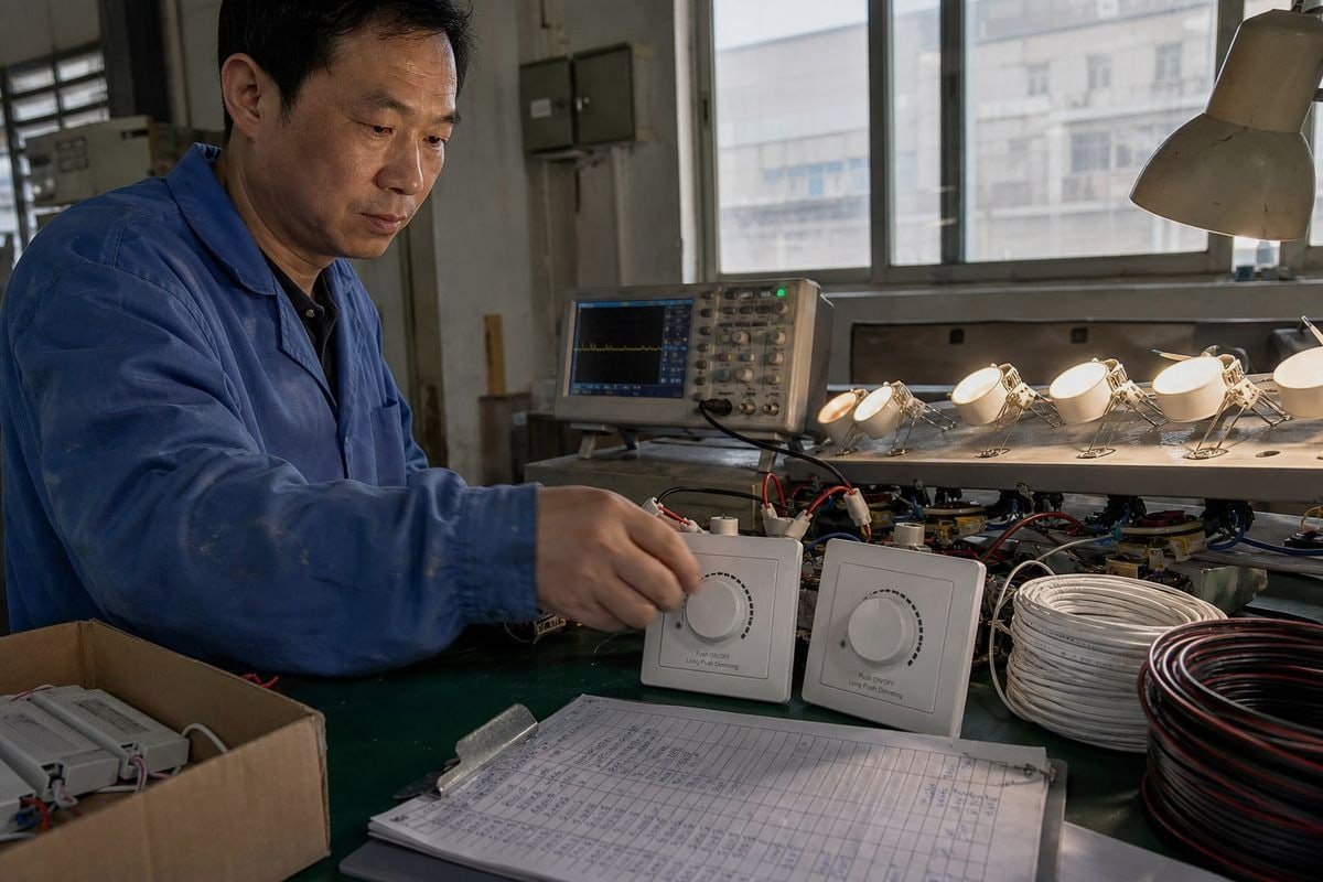
Leading edge vs trailing edge TRIAC dimmers สร้างความสับสนแม้แต่ผู้ซื้อที่มีประสบการณ์ บนสายการผลิตของเรา เราทดสอบทั้งสองแบบทุกวัน และการจับคู่ที่ไม่ตรงกันยังคงเป็นสาเหตุหลักของ[ข้อร้องเรียนเรื่องไฟกระพริบ](https://bo-qi.com/?p=6205)ที่เราได้รับ.
Leading edge vs trailing edge TRIAC dimmers เป็นทั้งคู่ที่เป็นเฟสคัทดิimmer แต่พวกมันตัดส่วนต่าง ๆ ของรูปคลื่น AC ออกไป ตัวลดแสงแบบ leading-edge (forward-phase) จะหน่วงการเปิดหลังจากแต่ละครึ่งรอบเริ่มต้น และมักใช้ TRIAC ในขณะที่ตัวลดแสงแบบ trailing-edge (reverse-phase) จะปิดก่อนที่ครึ่งรอบจะสิ้นสุด และมักใช้การสวิตชิ่งแบบ MOSFET สำหรับไฟ LED ไม่มีแบบใดที่ดีกว่ากันโดยสากล—การเลือกที่ถูกต้องขึ้นอยู่กับความเข้ากันได้ของเฟสคัทที่ระบุไว้ใน LED driver.
ความแตกต่างนั้นสำคัญมากกว่าที่หน้าผลิตภัณฑ์ส่วนใหญ่จะยอมรับ ให้ฉันอธิบายรายละเอียดให้คุณฟัง เพื่อให้คุณสามารถระบุ dimmers และ drivers ได้อย่างมั่นใจแทนการเดา.
ฉันจะรู้ได้อย่างไรว่าไดรเวอร์ LED ของฉันต้องใช้ตัวหรี่ไฟ TRIAC แบบ leading edge หรือ trailing edge?
ปีที่แล้ว ผู้ซื้อจากสิงคโปร์ส่งรูปไฟดาวน์ไลท์กระพริบสิบดวงมาให้เรา ช่างติดตั้งของเขาจับคู่ ไดรเวอร์ LED แบบหรี่แสงได้ด้วย TRIAC ของเรากับวอลล์ดิimmerแบบ reverse-phase ที่เข้ากันไม่ได้ การแก้ไขใช้เพียงอีเมลเดียว—แต่มันสอนให้เขาตรวจสอบสเปคก่อนเสมอ.
ตรวจสอบ datasheet หรือฉลากของ LED driver สำหรับคำว่า “forward phase,” “TRIAC,” “leading edge,” “reverse phase,” “ELV,” หรือ “trailing edge” ความเข้ากันได้ของเฟสคัทที่ระบุใน driver—และรายการความเข้ากันได้ของ dimmer ที่ทดสอบแล้ว—เป็นตัวกำหนดว่าต้องใช้ dimmer แบบใด ไม่ใช่ตัวโคมไฟหรือชื่อทางการตลาดของ dimmer.

Datasheet คือจุดเริ่มต้นของคุณ แต่ฉันอยากจะพูดตรง ๆ เกี่ยวกับสิ่งที่เราบอกลูกค้าวิศวกรทุกคน: การอ่านหนึ่งบรรทัดบนสเปคชีตไม่เพียงพอ นี่คือเหตุผล.
ตามสายสัญญาณ ไม่ใช่แค่ฉลาก
สายจริงมีลักษณะเช่นนี้: ไฟ AC หลัก → เฟสคัทดิimmer → บริดจ์เรกติไฟเออร์ 1 → bulk capacitor หรือ PFC stage → วงจร LED driver → โหลด LED เมื่อ dimmer ตัดรูปคลื่น AC driver ไม่ได้เพียงแค่รับแรงดันที่ลดลง ขั้นตอนอินพุตของมันได้รับรูปคลื่นที่ไม่ใช่ไซน์ซอยด์ที่มีช่วงการนำไฟฟ้าสั้นลง รูปคลื่นที่ถูกตัดนี้ส่งผลต่อกระแสพีคอินพุต การชาร์จ capacitor, กระแสพุ่งเข้า (Inrush Current) 2, TRIAC holding current, EMI, power factor, เสียงที่ได้ยิน, ระดับการลดแสงขั้นต่ำ, การกระพริบ และแม้แต่พฤติกรรมการเริ่มต้น.
นี่คือเหตุผลที่ LED drivers สองตัวที่ทั้งคู่ติดฉลากว่า “TRIAC dimmable” สามารถทำงานแตกต่างกันมากบนวอลล์ดิimmer ตัวเดียวกัน และนี่คือความแตกต่างที่เราเน้นย้ำกับลูกค้า OEM ทุกคน: LED driver ที่ลดแสงด้วย TRIAC ได้ไม่จำเป็นต้องเข้ากันได้กับทุก leading-edge dimmer ที่ระดับเอาต์พุตต่ำ dimmer อาจใช้ มุมการนำไฟฟ้า (Conduction Angle) 3, ที่สั้นมาก ในขณะที่ขั้นตอนอินพุตของ driver ยังต้องการพลังงานและ holding current เพียงพอที่จะทำงานต่อไป หากความต้องการเหล่านี้ไม่ตรงกัน คุณจะได้ไฟกระพริบ ไฟดับ, การติดทันที (Pop-on), dead travel หรือระดับแสงขั้นต่ำที่สูงอย่างน่าประหลาดใจ.
รายการตรวจสอบการระบุอย่างรวดเร็ว
- อ่าน datasheet ของ driver สำหรับคำว่า “forward phase,” “reverse phase,” “TRIAC,” หรือ “ELV”.
- มองหารายการความเข้ากันได้ของ dimmer ที่เผยแพร่จากผู้ผลิต driver.
- ตรวจสอบข้อกำหนดโหลดขั้นต่ำของ dimmer เทียบกับวัตต์รวมของวงจรคุณ.
- ยืนยันสเปคช่วงการลดแสง (เช่น 10%–100% เทียบกับ 1%–100%).
- เมื่อไม่แน่ใจ ให้ขอวิดีโอทดสอบบนโต๊ะจากซัพพลายเออร์—เราทำสิ่งนี้ทุกสัปดาห์ให้ลูกค้า.
ความแตกต่างหลักในประสิทธิภาพระหว่างการลดแสงแบบ leading edge และ trailing edge คืออะไร?
ข้อแลกเปลี่ยนหนึ่งที่เกิดขึ้นบ่อยในการตรวจสอบทางวิศวกรรมของเรา: ความหยาบของการสวิตชิ่งเทียบกับต้นทุน การควบคุมแบบ forward phase ถูกและทนทาน การควบคุมแบบ reverse phase นุ่มนวลและเงียบกว่า ไม่มีแบบใดชนะในทุกบรรทัด ดังนั้นให้ฉันอธิบายให้ชัดเจน.
การหรี่แสงแบบตัดขอบนำจะตัดส่วนหน้าของแต่ละครึ่งรอบไฟฟ้ากระแสสลับ ทำให้เกิดการเปิดเครื่องอย่างฉับพลันพร้อมกับกระแสพุ่งสูงและสัญญาณรบกวนแม่เหล็กไฟฟ้า การหรี่แสงแบบตัดขอบตามจะตัดส่วนท้ายของครึ่งรอบ ให้การเริ่มต้นที่นุ่มนวล การทำงานที่เงียบกว่า ความต้องการโหลดขั้นต่ำที่ต่ำกว่า และการหรี่แสงระดับต่ำที่ราบรื่นกว่ากับไดรเวอร์ LED ที่เข้ากันได้.
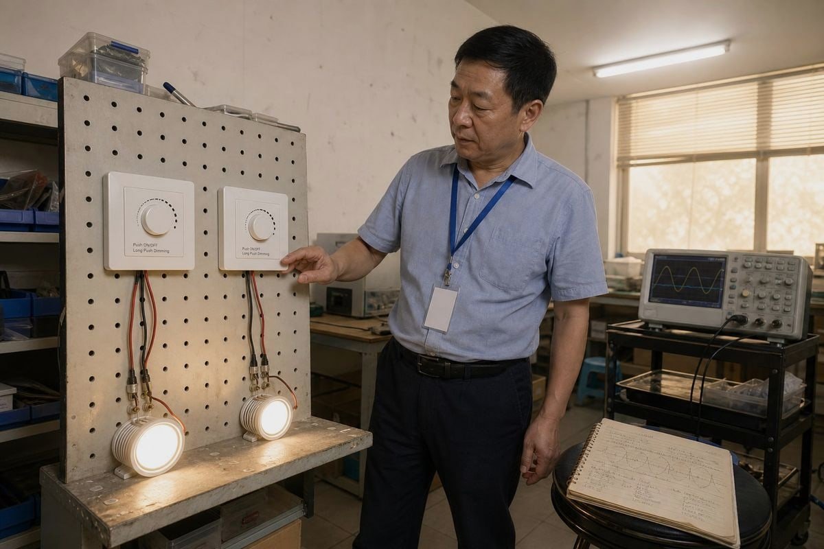
วิธีที่เร็วที่สุดในการเปรียบเทียบสอง topology คือการวางเคียงข้างกัน นี่คือรูปแบบตารางเดียวกับที่เรามอบให้ตัวแทนจำหน่ายระหว่างการเยี่ยมชมโรงงาน.
| ด้าน | ขอบนำ (เฟสไปข้างหน้า) | ขอบตาม (เฟสย้อนกลับ) |
|---|---|---|
| ตำแหน่งการตัด | ด้านหน้าของครึ่งรอบ AC | ปลายของครึ่งรอบ AC |
| อุปกรณ์สวิตชิ่งทั่วไป | ไตรแอก | มอสเฟต (MOSFET) |
| ความเหมาะสมของโหลดทั่วไป | หลอดไส้ ฮาโลเจน หม้อแปลงแม่เหล็กบางชนิด | LED drivers หลายตัว โหลดหม้อแปลงอิเล็กทรอนิกส์แรงดันต่ำ |
| พฤติกรรมการสวิตชิ่ง | การเปิดที่แข็งกระด้าง มี inrush current ที่ชัดเจน | การปิดที่นุ่มนวล การเปลี่ยนที่ราบรื่นกว่า |
| เสียง / EMI | โดยทั่วไปสูงกว่า | โดยทั่วไปต่ำกว่า |
| โหลดขั้นต่ำ | มักสูงกว่า เพื่อรักษา TRIAC ให้ทำงาน | มักจะต่ำกว่า บางครั้งระบุต่ำถึง 5–10W |
| ต้นทุน | มักจะต่ำกว่า | มักจะสูงกว่า |
หมายเหตุสำคัญเกี่ยวกับความแม่นยำก่อนที่เราจะไปต่อ เฟสไปข้างหน้าเป็นรูปแบบคลื่น TRIAC เป็นเพียงหนึ่งในการใช้งานทั่วไปของมัน หน้าการตลาดมักจะทำให้สับสนตลอดเวลา ดังนั้น “ตัวหรี่ TRIAC” จึงถูกใช้อย่างหลวมๆ เพื่อหมายถึงตัวหรี่แบบตัดเฟสใดๆ ก็ตาม แยกโทโพโลยีและอุปกรณ์สวิตชิ่งออกจากกันในหัวของคุณ แล้วความสับสนครึ่งหนึ่งในตลาดนี้จะหายไป.
ทำไมรูปร่างของคลื่นจึงขับเคลื่อนทุกอย่างอื่น
การหรี่แบบขอบนำช่วยให้กระแสไหลผ่านอย่างฉับพลันหลังจากการหน่วงเวลา ซึ่งทำให้เกิดกระแสพุ่งที่จุดเปิดสวิตช์ การพุ่งนั้นเหมาะกับโหลดแบบต้านทานและเหนี่ยวนำ เช่น ไส้หลอดฮาโลเจน แต่สร้างความเครียดให้กับอินพุตไดรเวอร์ LED แบบคาปาซิทีฟ และสร้างสัญญาณรบกวนแม่เหล็กไฟฟ้ามากขึ้น การหรี่แบบขอบตาม สร้างขึ้นบน เทคโนโลยี MOSFET 4, นำกระแสจากจุดศูนย์และปิดสวิตช์อย่างนุ่มนวลก่อนสิ้นสุดรอบ ผลลัพธ์คือการสวิตชิ่งที่นุ่มนวลกว่า เสียงหึ่งที่ได้ยินน้อยกว่า และทนทานต่อโหลดขนาดเล็กได้ดีกว่า.
มีข้อควรระวังเชิงปฏิบัติสองข้อที่เราชี้ให้ผู้ซื้อโครงการทราบ ประการแรก ตัวหรี่แบบขอบตามที่ใช้ MOSFET มีความไวต่ออุณหภูมิแวดล้อมมากกว่า TRIAC ดังนั้นกล่องผนังแบบหลายช่องจึงต้องมีการลดพิกัดกำลังไฟฟ้าที่เข้มงวดกว่า ประการที่สอง ไดรเวอร์ LED ระดับสูงที่มี PFC แบบแอคทีฟอาจขัดแย้งกับตัวหรี่แบบขอบตาม ซึ่งบางครั้งต้องใช้ตัวต้านทานบายพาสหรือโหลดจำลองเพื่อป้องกันแสงหลอนเมื่อปิดสวิตช์.
ฉันสามารถใช้ตัวหรี่แสงแบบขอบตามหลัง (trailing edge dimmer) กับไดรเวอร์ LED แบบหรี่แสงได้ด้วย TRIAC ใดๆ สำหรับโปรเจกต์ของฉันได้หรือไม่?
ตัวแทนจำหน่ายในเวียดนามเคยถามคำถามนี้กับฉันทาง WhatsApp ระหว่างการประกวดราคา โดยเหลือเวลาสองวันก่อนปิดสเปก ฉันต้องให้คำตอบที่ตรงไปตรงมากับเขา และมันเป็นคำตอบเดียวกับที่ฉันจะให้คุณที่นี่.
ไม่. ไดรเวอร์ LED แบบหรี่แสง TRIAC ถูกออกแบบมาสำหรับการควบคุมเฟสไปข้างหน้า ดังนั้น ตัวหรี่แสงแบบขอบตาม (เฟสย้อนกลับ) อาจทำให้เกิดการกะพริบ ช่วงการหรี่แสงจำกัด หรือไม่สามารถหรี่แสงได้เลย ควรจับคู่ตัวหรี่แสงแบบขอบตามกับไดรเวอร์ที่ระบุความเข้ากันได้กับเฟสย้อนกลับหรือ ELV อย่างชัดเจนในเอกสารข้อมูลเท่านั้น.

ไดรเวอร์บางตัวยอมรับทั้งสองวิธีแบบตัดเฟส หลายตัวไม่ยอมรับ ป้าย “หรี่ TRIAC ได้” หมายถึงความเข้ากันได้กับระบบเฟสไปข้างหน้าที่ใช้ TRIAC—มันอธิบายว่าอินพุตสเตจของไดรเวอร์ถูกออกแบบมาเพื่อตีความอะไร ป้อนคลื่นแบบเฟสย้อนกลับให้มัน วงจรตรวจจับอาจอ่านมุมการนำไฟฟ้าผิดทั้งหมด.
จุดซ่อนของกับดักคำศัพท์
ภาษาการตลาดยุ่งเหยิง หน้าผลิตภัณฑ์บางหน้าใช้ “ตัวหรี่ TRIAC” อย่างกว้างๆ แม้จะพูดถึงการหรี่ LED แบบตัดเฟสโดยทั่วไป คุณจะเจอความแตกต่างระหว่าง ELV กับ MLV ด้วย: ผลิตภัณฑ์ ELV (อิเล็กทรอนิกส์แรงดันต่ำ) คาดหวังการควบคุมแบบเฟสย้อนกลับ ในขณะที่ผลิตภัณฑ์ MLV (แม่เหล็กแรงดันต่ำ) คาดหวังการควบคุมแบบเฟสไปข้างหน้า เพราะโหลดหม้อแปลงเหนี่ยวนำไม่ชอบการปิดสวิตช์ฉับพลัน เมื่อเราสร้างไดรเวอร์ที่ปรับแต่งเองกับโลโก้ส่วนตัวของลูกค้า เราพิมพ์วิธีการตัดเฟสที่ยอมรับได้บนตัวเครื่องโดยตรงด้วยเหตุผลนี้—ช่างติดตั้งแทบไม่เคยอ่านดาต้าชีตบนบันได.
สิ่งที่เกิดขึ้นจริงเมื่อจับคู่ผิด
| อาการ | สาเหตุที่เป็นไปได้เมื่อตัดเฟสไม่ตรงกัน |
|---|---|
| ไฟกระพริบที่ระดับต่ำ | อินพุตไดรเวอร์ไม่สามารถตีความคลื่นที่ถูกตัดได้ |
| ปุ่มหมุนตายช่วง (Dead travel) | เส้นโค้งการหรี่ไม่ตรงกันระหว่างตัวหรี่และไดรเวอร์ |
| เปิดติดทันทีสว่าง (ไฟกระโดดสว่าง) | ไดรเวอร์ต้องการมุมการนำไฟฟ้าขั้นต่ำเพื่อเริ่มทำงาน |
| เสียงหึ่งจากโคมไฟหรือกล่องผนัง | ความเครียดจากคลื่นกระตุ้นชิ้นส่วนให้สั่นสะเทือนเป็นเสียง |
| แสงหลอนเมื่อปิด | กระแสรั่วไหลผ่านตัวหรี่ อาจต้องใช้โหลดบายพาส |
ทางออกอีกทางหนึ่งที่ควรรู้: ตัวหรี่แบบปรับเฟสอัตโนมัติหรือแบบสากลสมัยใหม่มีวงจรตรวจจับอัตโนมัติที่ทดสอบอิมพีแดนซ์โหลดตอนเริ่มต้นและสลับระหว่างโหมดขอบนำและขอบตามโดยอัตโนมัติ ราคาสูงกว่า แต่สำหรับโครงการปรับปรุงที่มีโหลดผสม มันลดความเสี่ยงได้มาก.

TRIAC dimmer ประเภทใดให้ความเข้ากันได้ดีกว่าและประสิทธิภาพไร้การกะพริบสำหรับโครงการวิศวกรรมแสงสว่างของฉัน?
บทเรียนที่ทีมวิศวกรของเราเรียนรู้หลังจากการส่งออกไปตลาดตั้งแต่ญี่ปุ่นถึงเยอรมนีเป็นเวลาหลายปี: ผู้ซื้อที่เลือกโดยโทโพโลยีเพียงอย่างเดียวมักโทรกลับมาด้วยปัญหา ผู้ซื้อที่เลือกโดยการจับคู่ที่ทดสอบแล้วไม่เป็นเช่นนั้น.
สำหรับการติดตั้ง LED สมัยใหม่หลายแห่ง การหรี่แบบขอบตามสามารถให้การทำงานที่นุ่มนวลและเงียบ โดยเฉพาะกับไดรเวอร์ที่ออกแบบมาสำหรับการควบคุมแบบเฟสย้อนกลับ อย่างไรก็ตาม ไดรเวอร์ LED ที่เข้ากันได้กับ TRIAC แบบขอบนำที่ออกแบบมาอย่างดีก็สามารถให้การหรี่ที่ยอดเยี่ยมได้เช่นกัน รายการความเข้ากันได้ที่ทดสอบแล้วของไดรเวอร์—ไม่ใช่แค่โทโพโลยีของตัวหรี่—ควรเป็นตัวกำหนดการเลือก.

ฉันรู้ว่าคำตอบนั้นฟังดูเด็ดขาดน้อยกว่า “ขอบตามชนะ” แต่มันเป็นคำตอบที่ยืนหยัดภายใต้การตรวจสอบทางเทคนิค และมันเป็นคำตอบที่ปกป้องงบประมาณโครงการของคุณ ขอบตามมักเหมาะกับไดรเวอร์ LED สมัยใหม่หลายตัว—ไม่ใช่ “ดีกว่าโดยทั่วไปสำหรับ LED” เป็นกฎครอบคลุม ความแตกต่างของถ้อยคำสำคัญ เพราะความเข้ากันได้ถูกกำหนดโดยการออกแบบอินพุตของไดรเวอร์ในที่สุด.
คู่มือการเลือกเชิงปฏิบัติตามประเภทโหลด
| โหลดของคุณ | วิธีการตัดเฟสที่แนะนำ |
|---|---|
| หลอดไส้ / ฮาโลเจน | ขอบนำ โหลดแบบต้านทานทนต่อการเปิดสวิตช์ฉับพลันได้ดี |
| ไดรเวอร์ LED ที่ระบุเฟสไปข้างหน้าเท่านั้น | ตัวหรี่ TRIAC แบบขอบนำจากรายการที่ทดสอบแล้วของไดรเวอร์ |
| ไดรเวอร์ LED ที่ระบุเฟสย้อนกลับ / ELV | ตัวหรี่แบบขอบตาม จับคู่กับรายการความเข้ากันได้ |
| โหลดหม้อแปลงอิเล็กทรอนิกส์แรงดันต่ำ | ขอบตาม อ่อนโยนต่ออุปกรณ์อิเล็กทรอนิกส์แบบคาปาซิทีฟ |
| หม้อแปลงแม่เหล็ก (MLV) | ขอบนำ ตรวจสอบกับผู้ผลิตหม้อแปลง |
| วงจรปรับปรุงแบบผสมหรือไม่ทราบชนิด | ตัวหรี่สากลแบบปรับเฟสอัตโนมัติ |
ประสิทธิภาพไร้การกระพริบมาจากไหนจริงๆ
การลดแสงแบบไร้การกะพริบเป็นคุณสมบัติของระบบ ไม่ใช่คุณสมบัติของชิ้นส่วน อาการกะพริบและเสียงฮัมของ LED มักย้อนกลับไปที่ความไม่สอดคล้องสามประการ: มุมการนำไฟฟ้าของตัวลดแสงที่ระดับต่ำตกลงต่ำกว่าความต้องการของไดรเวอร์ เส้นโค้งการลดแสงของไดรเวอร์ขัดแย้งกับเส้นโค้งเอาต์พุตของตัวลดแสง และการป้องกันกระแสไฟกระชากหรือการออกแบบ bleeder ที่ไม่เพียงพอในการจับคู่ นี่คือเหตุผลที่เราเผยแพร่ชุดค่าผสมที่ทดสอบแล้วสำหรับตัวลดแสง TRIAC และไดรเวอร์ของเรา และเหตุผลที่เราแนะนำให้ลูกค้าขอตัวอย่างคู่ก่อนที่จะยืนยันปริมาณโครงการ การทดสอบตัวอย่างมูลค่ายี่สิบดอลลาร์ช่วยประหยัดการประกวดราคามากกว่าหนึ่งครั้งจากข้อพิพาทการรับประกัน.
แนวโน้มสองประการที่ควรจับตามองเช่นกัน ตัวลดแสง TRIAC แบบดั้งเดิมยังคงครองตลาดการปรับปรุงและติดตั้งแบบประหยัดเพราะคุ้นเคยและราคาถูก ในขณะเดียวกัน ตัวลดแสงอัจฉริยะรุ่นใหม่กำลังเคลื่อนไปสู่สถาปัตยกรรมดิจิทัลแบบไฮบริดที่ให้ผู้ใช้ปรับเทียบเส้นโค้งการลดแสงที่กำหนดเองผ่านเฟิร์มแวร์ กำจัดช่วงการเคลื่อนที่ที่ตายแล้วที่ด้านล่างของช่วง สำหรับบริษัทวิศวกรรมที่ระบุวันนี้โดยมองถึงอนาคต ความยืดหยุ่นของเฟิร์มแวร์นั้นเป็นตัวสร้างความแตกต่างอย่างแท้จริง.
บทสรุป
Leading edge หมายถึง forward phase: การเปิดจะล่าช้าหลังจากแต่ละครึ่งรอบเริ่มต้น Trailing edge หมายถึง reverse phase: การปิดเกิดขึ้นก่อนแต่ละครึ่งรอบสิ้นสุด TRIAC มักขับเคลื่อนการลดแสงแบบ leading edge MOSFET มักขับเคลื่อนการลดแสงแบบ trailing edge ไม่มีแบบใดที่ดีกว่าโดยเนื้อแท้สำหรับ LED—ตัวเลือกที่ดีที่สุดคือวิธีการตัดเฟสที่ขั้นตอนอินพุตของไดรเวอร์ LED ของคุณรองรับโดยเฉพาะ จับคู่ชุดที่ทดสอบแล้ว ตรวจสอบข้อกำหนดโหลดขั้นต่ำ และโครงการของคุณจะไร้การกะพริบ.
เชิงอรรถ
- กำหนดส่วนประกอบการเรียงกระแสในขั้นตอนอินพุตของไดรเวอร์ LED. ↩︎
- อธิบายกระแสไฟกระชากเริ่มต้นที่เกิดขึ้นระหว่างการเปิดการลดแสงแบบ leading-edge. ↩︎
- อธิบายระยะเวลาการไหลของกระแสในรูปคลื่นแบบตัดเฟสซึ่งส่งผลต่อความเสถียรของการลดแสง. ↩︎
- ให้ข้อมูลทางเทคนิคเกี่ยวกับอุปกรณ์เซมิคอนดักเตอร์ที่ใช้ในการลดแสงแบบ reverse-phase. ↩︎