Hoppa till innehåll










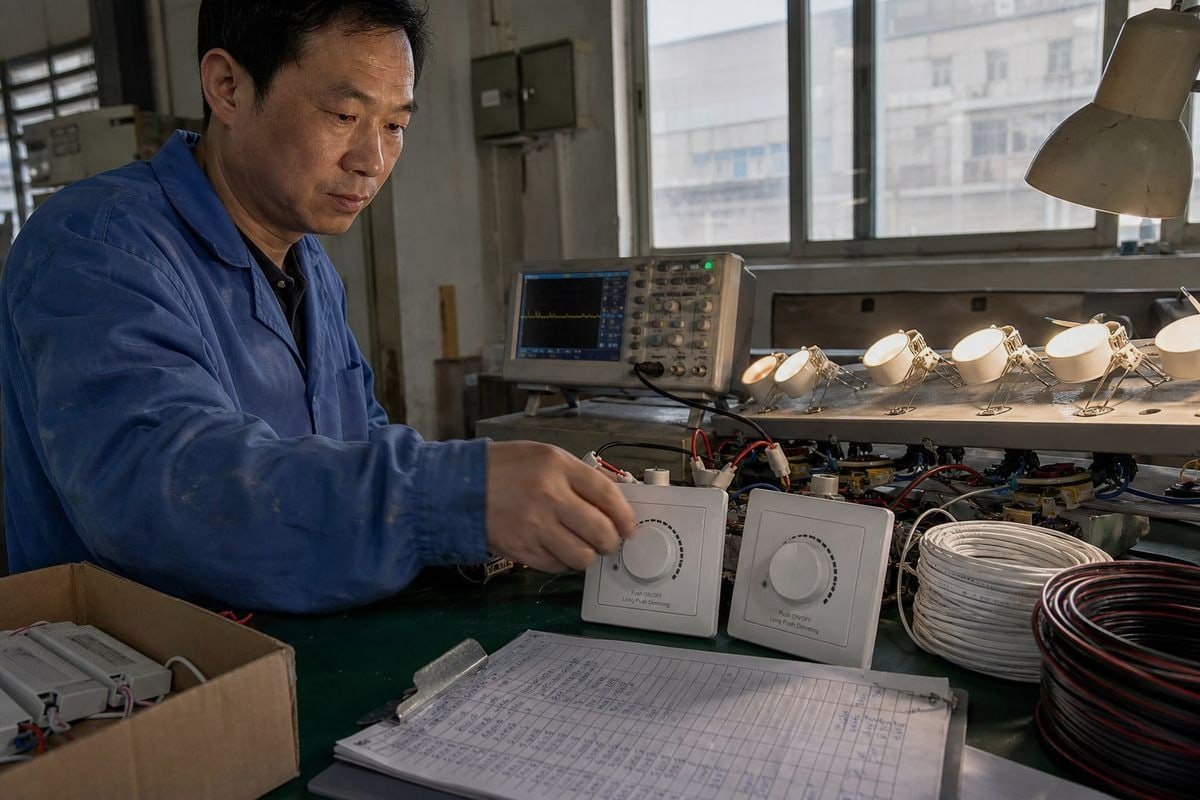
TRIAC-dimmer av typen ”leading edge” respektive ”trailing edge” kan förvirra även erfarna köpare. På vår produktionslinje testar vi båda varianterna dagligen, och felaktiga kombinationer är fortfarande orsaken till de flesta [klagomål om flimmer](https://bo-qi.com/?p=6205) som vi får.
Både leading-edge- och trailing-edge-TRIAC-dimmer är fasavskärningsdimmer, men de avskär olika delar av växelströmsvågformen. En förspänningsdimmer (framfas) fördröjer tändningen efter att varje halvcykel har börjat och använder vanligtvis en TRIAC, medan en bakspänningsdimmer (bakfas) stänger av innan halvcykeln avslutas och vanligtvis använder MOSFET-baserad omkoppling. För LED-belysning är ingen av dem generellt sett bättre – det rätta valet beror på LED-drivrutinens angivna kompatibilitet med fasavskärning.
Denna skillnad är viktigare än vad de flesta produktsidor ger uttryck för. Låt mig gå igenom detaljerna med dig, så att du kan välja dimmer och drivdon med säkerhet istället för att gissa dig fram.
Hur vet jag om min LED-drivkrets kräver en TRIAC-dimmer av typen ”leading edge” eller ”trailing edge”?
Förra året skickade en kund från Singapore ett foto till oss på tio flimrande spotlampor. Hans installatör hade kopplat ihop våra TRIAC-dimerbara LED-drivdon med en väggdimmer av omvänd fas som inte var kompatibel. Det räckte med ett e-postmeddelande för att lösa problemet – men det lärde honom att först kontrollera specifikationerna.
Kontrollera om det står “forward phase”, “TRIAC”, “leading edge”, “reverse phase”, “ELV” eller “trailing edge” i LED-drivrutinens datablad eller på etiketten. Drivrutinens angivna kompatibilitet med fasavskärning – samt dess testade lista över kompatibla dimmare – avgör vilken typ av dimmer som krävs, inte armaturens eller dimmerns marknadsföringsnamn.

Databladet är din utgångspunkt, men jag vill vara ärlig om något som vi alltid säger till våra kunder inom teknikbranschen: det räcker inte att läsa en enda rad i ett specifikationsblad. Här är varför.
Följ signalkedjan, inte bara etiketten
Den faktiska kedjan ser ut så här: växelströmsnätet → fasavbrytande dimmer → brygglikriktare 1 → bulk-kondensator eller PFC-steg → LED-drivkrets → LED-belastning. När dimmern avbryter växelströmsvågformen får drivkretsen inte bara en lägre spänning. Dess ingångssteg tar emot en icke-sinusformad vågform med en förkortad ledningsperiod. Denna avbrutna vågform påverkar ingångens toppström, kondensatorladdningen, startström 2, TRIAC:s hållström, elektromagnetisk störning (EMI), effektfaktor, ljudnivå, lägsta dimningsnivå, flimmer och till och med startbeteende.
Det är just därför som två LED-drivdon som båda är märkta som “TRIAC-dimmbara” kan fungera väldigt olika när de ansluts till samma väggdimmer. Och här är den skillnad som vi betonar för alla våra OEM-kunder: ett TRIAC-dimmbart LED-drivdon är inte nödvändigtvis kompatibelt med alla leading-edge-dimmer. Vid låga uteffekter kan dimmern ha en mycket kort ledningsvinkel 3, medan drivkretsens ingångssteg fortfarande behöver tillräckligt med energi och hållström för att fortsätta fungera. Om dessa krav inte stämmer överens uppstår flimmer, avbrott, pop-on, resor i mörker eller en överraskande hög miniminivå för belysningen.
En snabb checklista för identifiering
- Läs drivkretsens datablad för att se om begreppen “framåtriktad fas”, “bakåtriktad fas”, “TRIAC” eller “ELV” förekommer.
- Leta efter en offentliggjord lista över kompatibla dimmer från drivrutinstillverkaren.
- Kontrollera att dimmerns minsta belastningskrav överensstämmer med den totala effekten i kretsen.
- Kontrollera specifikationerna för dimningsområdet (till exempel 10%–100% jämfört med 1%–100%).
- Om du är osäker, be leverantören om en video från ett bänktest – vi genomför sådana varje vecka åt våra kunder.
Vilka är de viktigaste skillnaderna i prestanda mellan dimning vid framkanten och dimning vid bakkanten?
En avvägning som ständigt dyker upp i våra tekniska granskningar är valet mellan skakighet och kostnad. Framåtriktad fasstyrning är billig och robust. Bakåtriktad fasstyrning är mjukare och tystare. Ingen av dem vinner på alla punkter, så låt mig förklara det tydligt.
Vid framkantdämpning avbryts början av varje växelströmshalvcykel, vilket ger en abrupt tändning med högre startström och elektromagnetisk störning. Vid bakkantdämpning avbryts slutet av halvcykeln, vilket ger en mjuk start, tystare drift, lägre minimikrav på belastning och jämnare dämpning i det lägre området med kompatibla LED-drivkretsar.

Det snabbaste sättet att jämföra de två topologierna är att ställa dem bredvid varandra. Det här är samma tabellformat som vi delar ut till distributörerna vid fabriksbesök.
| Aspekt | Framkant (framåtriktad fas) | Bakkant (omvänd fas) |
|---|---|---|
| Skärposition | Framsidan av luftkonditioneringens halvcykel | Slutet på växelströmens halvcykel |
| Vanlig kopplingsanordning | TRIAC | MOSFET |
| Typisk lastanpassning | Glödlampor, halogenlampor, vissa magnetiska transformatorer | Många LED-drivkretsar, elektroniska lågspänningstransformatorer |
| Bytbeteende | Kraftig startström, märkbar startström | Mjuk avstängning, mjukare övergångar |
| Buller / EMI | Generellt sett högre | Generellt sett lägre |
| Minsta last | Ofta högre, för att hålla TRIAC:en påslagen | Ofta lägre, ibland anges så lågt som 5–10 W |
| Kostnad | Ofta lägre | Ofta högre |
En viktig precisering innan vi går vidare. Framfas är en vågformstopologi; TRIAC är bara en vanlig tillämpning av den. Marknadsföringssidor blandar ständigt ihop detta, vilket gör att begreppet “TRIAC-dimmer” ofta används i vid bemärkelse för att beteckna vilken fasavskärningsdimmer som helst. Håll isär topologi och kopplingsenhet i tankarna, så försvinner hälften av förvirringen på denna marknad.
Varför vågformens utseende styr allt annat
Vid framkantdämpning släpps strömmen igenom plötsligt efter en fördröjning, vilket ger upphov till en strömstöt vid tillkoppling. Denna strömstöt passar resistiva och induktiva laster, såsom halogenlampor, men belastar kapacitiva ingångar på LED-drivkretsar och ger upphov till mer elektromagnetisk störning. Bakkantdämpning, som bygger på MOSFET-teknik 4, styr från nollgenomgången och stängs av mjukt innan cykeln avslutas. Resultatet blir mjukare omkoppling, mindre hörbart surr och bättre tolerans för små belastningar.
Det finns två praktiska saker som vi vill uppmärksamma projektköpare på. För det första är MOSFET-baserade bakkantdimmer mer känsliga för omgivningstemperaturen än TRIAC-dimmer, vilket innebär att flerfacksväggdosor kräver en strängare nedgradering av effekten. För det andra kan avancerade LED-drivkretsar med aktiv PFC orsaka konflikter med bakkantdimmer, vilket ibland kräver en avledningsledare eller en attrappbelastning för att förhindra spökbildning när strömbrytaren är avstängd.
Kan jag använda en dimmer med bakkantstyrning tillsammans med vilken TRIAC-dimmbar LED-drivkrets som helst i mitt projekt?
En distributör i Vietnam ställde en gång precis den här frågan till mig via WhatsApp, mitt under en anbudsprocess, med två dagar kvar till att lämna in sitt anbud. Jag var tvungen att ge honom ett ärligt svar, och det är samma svar som jag kommer att ge dig här.
Nej. En TRIAC-dimbar LED-drivkrets är avsedd för framfasstyrning, så en bakfasdimmer (omvänd fas) kan orsaka flimmer, ett begränsat dimningsområde eller att dimningen inte fungerar alls. Använd endast en bakfasdimmer tillsammans med drivkretsar där kompatibilitet med omvänd fas eller ELV uttryckligen anges i databladet.
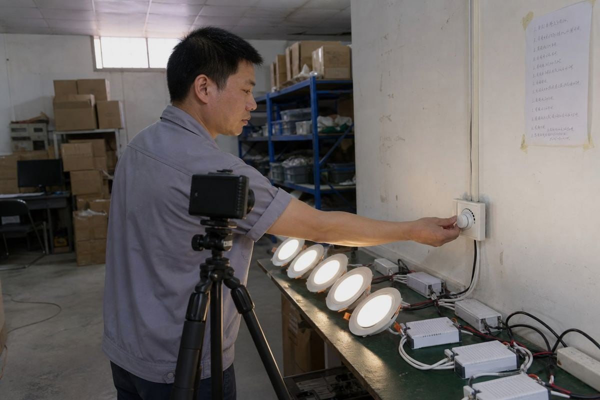
Vissa drivkretsar klarar båda fasavskärningsmetoderna. Många gör det inte. Beteckningen “TRIAC-dimbar” avser kompatibilitet med TRIAC-baserade framfas-system – den beskriver vad drivkretsens ingångssteg är konstruerat för att tolka. Om den matas med en bakfasvågform kan detekteringskretsen helt felaktigt tolka ledningsvinkeln.
Var terminologins fallgropar lurar
Marknadsspråket är rörigt. På vissa produktsidor används begreppet “TRIAC-dimmer” i vid bemärkelse, även när man talar om fasavskärningsdämpning av LED-belysning i allmänhet. Du kommer också att stöta på distinktionen mellan ELV och MLV: ELV-produkter (elektronisk lågspänning) kräver fasomvänd styrning, medan MLV-produkter (magnetisk lågspänning) kräver fasriktad styrning, eftersom induktiva transformatorbelastningar inte tål plötslig avstängning. När vi tillverkar skräddarsydda drivdon med kundens egen logotyp trycker vi den godkända fasavskärningsmetoden direkt på höljet just av denna anledning – installatörer läser sällan datablad när de står på en stege.
Vad händer egentligen om man parar ihop fel par?
| Symtom | Trolig orsak vid felaktig fasavskärning |
|---|---|
| Flimmer vid låga inställningar | Driver-inmatningen kan inte tolka den avbrutna vågformen |
| Döda färdas på knoppen | Avvikelse i dimningskurvan mellan dimmer och drivdon |
| Pop-on (belysningen skiftar till starkt ljus) | Föraren behöver en viss minsta ledningsvinkel för att kunna starta |
| Surret från armaturen eller vägguttaget | Vågform som akustiskt exciterar komponenter |
| Ghosting när den är avstängd | Läckström genom dimmern; en avlastningslast kan behövas |
Ytterligare en lösning som är värd att känna till: moderna fasadaptiva eller universella dimmer har en automatisk avkänningskrets som mäter belastningens impedans vid start och automatiskt växlar mellan ledande- och efterkantläge. De kostar mer, men vid renoveringsprojekt med blandad belastning minskar de risken avsevärt.

Vilken typ av TRIAC-dimmer erbjuder bättre kompatibilitet och flimmerfri drift för mina belysningsprojekt?
Den lärdom som vårt teknikteam dragit efter flera års export till marknader från Japan till Tyskland är följande: köpare som väljer enbart utifrån topologi ringer tillbaka med problem; köpare som väljer utifrån beprövade kombinationer gör det inte.
I många moderna LED-installationer kan bakkantdimning ge en jämn och tyst drift, särskilt med drivdon som är utformade för omvänd fasstyrning. Men även ett välkonstruerat framkant-TRIAC-kompatibelt LED-drivdon kan ge utmärkt dimning. Valet bör baseras på drivdonets testade kompatibilitetslista – inte enbart på dimmerns topologi.

Jag vet att det svaret känns mindre entydigt än “trailing edge vinner”. Men det är det svar som håller vid en teknisk granskning, och det är det som skyddar din projektbudget. Trailing edge passar ofta bättre för många moderna LED-drivdon – inte “generellt bättre för LED” som en generell regel. Skillnaden i formulering är viktig, eftersom kompatibiliteten i slutändan avgörs av drivdonets ingångskonstruktion.
En praktisk urvalsguide efter lasttyp
| Din last | Rekommenderad metod för fasavskärning |
|---|---|
| Glödlampa / halogenlampa | Framkant; resistiva laster klarar den plötsliga tillkopplingen väl |
| LED-drivkretsar avsedda endast för framåtriktad fas | En toppmodern TRIAC-dimmer från förarens testlista |
| LED-drivdon klassade som omvänd fas / ELV | Dimmer för bakkant, enligt kompatibilitetslistan |
| Elektroniska lågspänningstransformatorbelastningar | Bakkant; skonsammare mot kapacitiv elektronik |
| Magnetiska transformatorer (MLV) | Framkant, verifierad av transformatortillverkaren |
| Blandade eller okända eftermonterade kretsar | Fasanpassad universaldimmer |
Varifrån den flimmerfria prestandan egentligen kommer
Flimmerfri dimning är en systemegenskap, inte en komponentegenskap. LED-flimmer och surrande ljud beror vanligtvis på tre typer av inkompatibilitet: att dimmerns ledningsvinkel vid låga inställningar understiger drivkretsens krav, att drivkretsens dimningskurva står i konflikt med dimmerns utgångskurva, samt otillräckligt skydd mot startström eller bristfällig utjämningsdesign i kombinationen. Det är därför vi publicerar testade kombinationer för våra TRIAC-dimmer och drivdon, och varför vi rekommenderar att kunderna begär provpar innan de beställer en projektkvantitet. Ett provtest på tjugo dollar har räddat mer än en upphandling från en garantitvist.
Det finns också två trender som är värda att hålla ett öga på. Äldre TRIAC-dimmer dominerar fortfarande eftermonteringar och budgetinstallationer eftersom de är välbekanta och billiga. Samtidigt går nästa generations smarta dimmer mot hybriddigitala arkitekturer som låter användarna kalibrera anpassade dimningskurvor via firmware, vilket eliminerar dödgång i nedre delen av intervallet. För ingenjörsföretag som specificerar idag med blicken riktad mot morgondagen är denna firmwareflexibilitet en verklig konkurrensfördel.
Slutsats
Framkant innebär framåtfas: tändningen fördröjs efter att varje halvcykel har börjat. Bakkant innebär bakåtfas: avstängningen sker innan varje halvcykel avslutas. TRIAC-komponenter används vanligtvis för framkantdämpning, medan MOSFET-komponenter vanligtvis används för bakkantdämpning. Ingen av metoderna är i sig bättre för LED-lampor – det bästa valet är den fasavskärningsmetod som ingångssteget i din LED-drivkrets specifikt stöder. Använd beprövade kombinationer, kontrollera minimikraven för belastning, så blir ditt projekt flimmerfritt.
Fotnoter
- Definierar likriktarkomponenten i LED-drivrutinens ingångssteg. ↩︎
- Förklarar den inledande strömspiken som uppstår vid aktivering av dimning vid framkant. ↩︎
- Beskriver hur länge strömmen flödar i fasavskurna vågformer, vilket påverkar dimningens stabilitet. ↩︎
- Ger teknisk bakgrundsinformation om de halvledarkomponenter som används vid dämpning med omvänd fas. ↩︎