Pular para o conteúdo










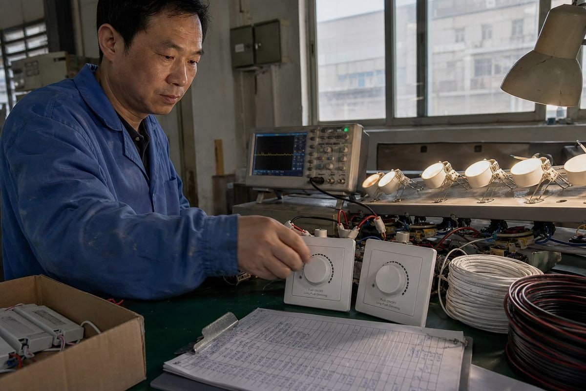
Os reguladores de intensidade de luz TRIAC de «borda de ataque» e de «borda de fuga» confundem até mesmo os compradores mais experientes. Na nossa linha de produção, testamos ambos diariamente, e as combinações inadequadas continuam a ser a causa da maioria das [queixas relativas à oscilação da luz](https://bo-qi.com/?p=6205) que recebemos.
Os reguladores de intensidade de luz com TRIAC de «borda ascendente» e de «borda descendente» são ambos reguladores de corte de fase, mas removem partes diferentes da forma de onda de corrente alternada. Um regulador de intensidade de fase ascendente (fase direta) atrasa o acendimento após o início de cada meio-ciclo e utiliza normalmente um TRIAC, enquanto um regulador de intensidade de fase descendente (fase inversa) desliga antes do fim do meio-ciclo e utiliza normalmente comutação baseada em MOSFET. No caso da iluminação LED, nenhum dos dois é universalmente melhor — a escolha correta depende da compatibilidade de corte de fase especificada pelo controlador de LED.
Essa distinção é mais importante do que a maioria das páginas de produtos admite. Deixa-me explicar-te os pormenores, para que possas escolher reguladores de intensidade e controladores com confiança, em vez de teres de adivinhar.
Como posso saber se o meu controlador de LED necessita de um regulador de intensidade TRIAC de flanco ascendente ou descendente?
No ano passado, um comprador de Singapura enviou-nos uma fotografia de dez luzes embutidas que piscavam. O seu instalador tinha emparelhado os nossos Controladores LED reguláveis por TRIAC com um regulador de intensidade de luz de parede de fase inversa incompatível. A solução exigiu apenas um e-mail — mas ensinou-o a verificar primeiro as especificações.
Consulte a ficha técnica ou a etiqueta do controlador de LED para verificar se constam os termos “fase direta”, “TRIAC”, “borda ascendente”, “fase inversa”, “ELV” ou “borda descendente”. É a compatibilidade com corte de fase indicada pelo controlador — e a sua lista de compatibilidade com reguladores testada — que determina o tipo de regulador necessário, e não o nome comercial da luminária ou do regulador.

A ficha técnica é o seu ponto de partida, mas quero ser sincero sobre algo que dizemos a todos os nossos clientes da área da engenharia: não basta ler uma única linha de uma ficha técnica. Eis o motivo.
Segue a cadeia de sinal, não apenas a etiqueta
O circuito real tem o seguinte aspeto: rede de corrente alternada → regulador de intensidade com corte de fase → retificador em ponte 1 → condensador de grande capacidade ou etapa de PFC → circuito controlador de LED → carga de LED. Quando o regulador de intensidade interrompe a forma de onda CA, o controlador não recebe simplesmente uma tensão mais baixa. A sua etapa de entrada recebe uma forma de onda não sinusoidal com um período de condução mais curto. Essa forma de onda interrompida afeta a corrente de pico de entrada, o carregamento do condensador, corrente de arranque 2, corrente de retenção do TRIAC, EMI, fator de potência, ruído audível, nível mínimo de regulação de intensidade, cintilação e até mesmo o comportamento no arranque.
É precisamente por isso que dois controladores de LED, ambos rotulados como “reguláveis por TRIAC”, podem comportar-se de forma muito diferente no mesmo regulador de parede. E eis a distinção que salientamos a todos os nossos clientes OEM: um controlador de LED regulável por TRIAC não é necessariamente compatível com todos os reguladores de corte de frente. A níveis de potência baixos, o regulador pode funcionar durante um período muito curto ângulo de condução 3, enquanto o estágio de entrada do controlador ainda necessita de energia e corrente de manutenção suficientes para se manter ativo. Se esses requisitos não corresponderem, ocorrem oscilações de luminosidade, falhas de alimentação, pop-on, percurso sem tráfego ou um nível mínimo de luminosidade surpreendentemente elevado.
Uma lista de verificação rápida para identificação
- Consulte a ficha técnica do controlador para verificar se contém as menções “fase direta”, “fase inversa”, “TRIAC” ou “ELV”.
- Procure uma lista de compatibilidade com reguladores de intensidade de luz publicada pelo fabricante do controlador.
- Verifique os requisitos mínimos de carga do regulador de intensidade em relação à potência total do circuito.
- Confirme as especificações do intervalo de regulação de intensidade (por exemplo, 10%–100% vs 1%–100%).
- Em caso de dúvida, peça ao fornecedor um vídeo de um teste de bancada — realizamos estes testes semanalmente para os nossos clientes.
Quais são as principais diferenças de desempenho entre o escurecimento na borda de ataque e o escurecimento na borda de fuga?
Há um compromisso que surge constantemente nas nossas análises de engenharia: a escolha entre a aspereza da comutação e o custo. O controlo de fase direta é económico e robusto. O controlo de fase inversa é mais suave e silencioso. Nenhum dos dois se destaca em todos os aspetos, por isso vou explicar isto com clareza.
A regulação de intensidade de ponta de frente corta a parte inicial de cada meio ciclo de corrente alternada, produzindo um acendimento abrupto com maior corrente de arranque e interferência eletromagnética (EMI). A regulação de intensidade de ponta de cauda corta o final do meio ciclo, proporcionando um arranque suave, um funcionamento mais silencioso, requisitos de carga mínima mais baixos e uma regulação de intensidade mais suave em níveis baixos com controladores de LED compatíveis.
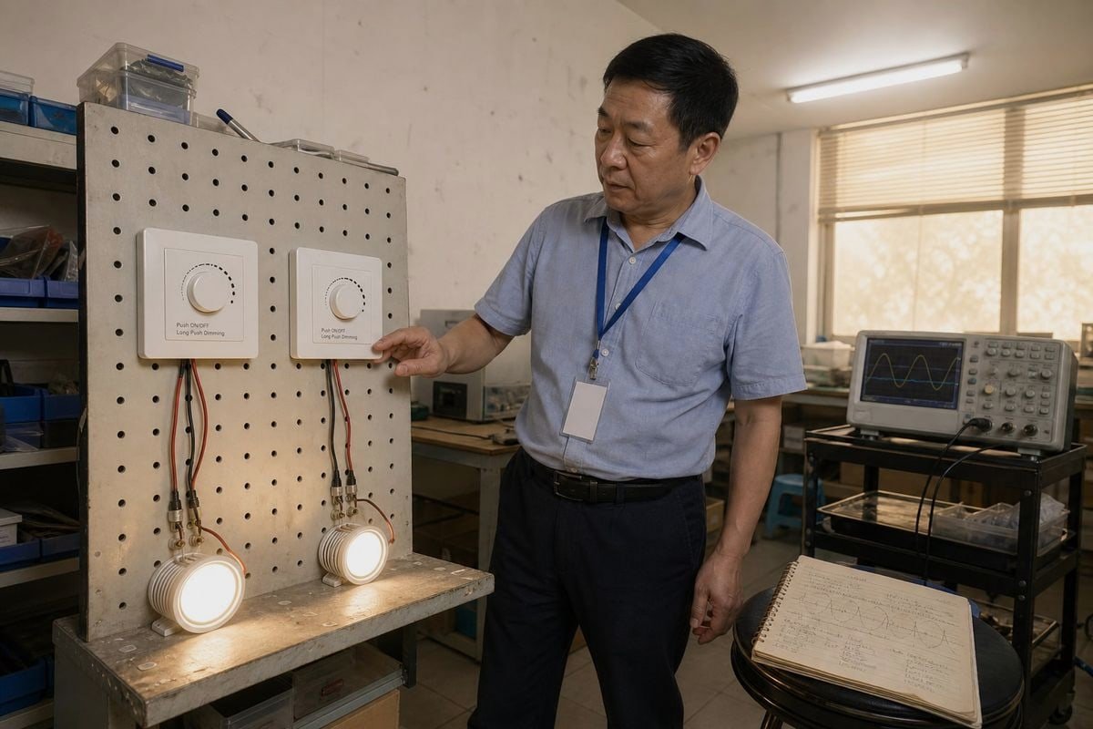
A forma mais rápida de comparar as duas topologias é colocá-las lado a lado. Este é o mesmo formato de tabela que entregamos aos distribuidores durante as visitas à fábrica.
| Aspeto | Borda de ataque (fase de avanço) | Borda de saída (fase inversa) |
|---|---|---|
| Posição de corte | Parte inicial do meio-ciclo do ar condicionado | Fim do semiciclo de corrente alternada |
| Dispositivo de comutação comum | TRIAC | MOSFET |
| Ajuste típico da carga | Lâmpadas incandescentes, halógenas e alguns transformadores magnéticos | Muitos controladores de LED, cargas de transformadores eletrónicos de baixa tensão |
| Comportamento de comutação | Arranque em carga, corrente de arranque significativa | Desligamento suave, transições mais suaves |
| Ruído / Interferência eletromagnética (EMI) | Geralmente mais elevado | Geralmente mais baixo |
| Carga mínima | Frequentemente mais elevado, para manter o TRIAC ligado | Frequentemente mais baixo, sendo por vezes referido como sendo de apenas 5–10 W |
| Custo | Frequentemente mais baixo | Frequentemente mais elevado |
Uma observação importante antes de prosseguirmos. A fase direta é uma topologia de forma de onda; o TRIAC é apenas uma das suas implementações mais comuns. As páginas de marketing confundem constantemente estes conceitos, pelo que a expressão “regulador de intensidade com TRIAC” é utilizada de forma imprecisa para designar qualquer regulador de intensidade com corte de fase. Se mantiveres a topologia e o dispositivo de comutação separados na tua mente, metade da confusão neste mercado desaparecerá.
Por que razão a forma da onda determina tudo o resto
A regulação de intensidade de ponta de subida permite que a corrente passe abruptamente após um atraso, o que produz um pico de corrente no momento da ativação. Esse pico é adequado para cargas resistivas e indutivas, como filamentos halógenos, mas sobrecarrega as entradas capacitivas dos controladores de LED e gera mais interferência eletromagnética. A regulação de intensidade de ponta de descida, baseada em Tecnologia MOSFET 4, conduz a partir da passagem por zero e desliga-se suavemente antes do fim do ciclo. O resultado é uma comutação mais suave, menos zumbido audível e uma melhor tolerância a cargas pequenas.
Há duas ressalvas práticas que chamamos a atenção dos compradores de projetos. Em primeiro lugar, os reguladores de intensidade de luz de borda descendente baseados em MOSFET são mais sensíveis à temperatura ambiente do que os TRIACs, pelo que as caixas de parede com várias tomadas exigem uma redução mais rigorosa da potência nominal. Em segundo lugar, os controladores LED de gama alta com PFC ativo podem entrar em conflito com os reguladores de intensidade de luz de borda descendente, exigindo, por vezes, uma carga de descarga ou uma carga fictícia para evitar o efeito de «fantasma» quando o interruptor está desligado.
Posso utilizar um regulador de intensidade de luz do tipo «trailing edge» com qualquer controlador LED regulável por TRIAC no meu projeto?
Um distribuidor no Vietname fez-me uma vez exatamente esta pergunta pelo WhatsApp, a meio de um concurso, faltando dois dias para o prazo de apresentação da proposta. Tive de lhe dar uma resposta sincera, e é a mesma que vos vou dar aqui.
Não. Um controlador LED regulável com TRIAC foi concebido para controlo de fase direta, pelo que um regulador de fase inversa (trailing-edge) pode causar cintilação, limitar a amplitude de regulação ou impedir completamente a regulação. Utilize um regulador de fase inversa apenas com controladores que indiquem explicitamente, na ficha técnica, compatibilidade com fase inversa ou ELV.
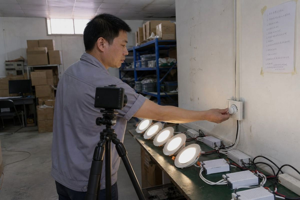
Alguns controladores aceitam ambos os métodos de corte de fase. Muitos não. A indicação “regulável por TRIAC” refere-se à compatibilidade com sistemas de fase direta baseados em TRIAC — descreve o que o estágio de entrada do controlador foi concebido para interpretar. Se lhe for fornecida uma forma de onda de fase inversa, o circuito de deteção poderá interpretar o ângulo de condução de forma totalmente errada.
Onde se escondem as armadilhas da terminologia
A terminologia do mercado é confusa. Algumas páginas de produtos utilizam o termo “regulador TRIAC” de forma genérica, mesmo quando se refere à regulação de LED por corte de fase em geral. Também se deparará com a distinção entre ELV e MLV: os produtos ELV (baixa tensão eletrónica) requerem controlo de fase inversa, enquanto os produtos MLV (baixa tensão magnética) requerem controlo de fase direta, uma vez que as cargas de transformadores indutivos não toleram o desligamento abrupto. Quando fabricamos controladores personalizados com o logótipo privado de um cliente, imprimimos o método de corte de fase aceite diretamente na caixa precisamente por esta razão — os instaladores raramente lêem fichas técnicas enquanto trabalham nas escadas.
O que acontece, na verdade, quando se faz um emparelhamento errado
| Sintoma | Causa provável devido a um desfasamento incorreto |
|---|---|
| Cintilação em configurações baixas | A entrada do controlador não consegue interpretar a forma de onda fragmentada |
| Os mortos viajam no botão | Incompatibilidade da curva de regulação de intensidade entre o regulador de intensidade e o controlador |
| Pop-on (a luz passa de fraca para intensa) | O condutor necessita de um ângulo de condução mínimo para arrancar |
| Zumbido proveniente do candeeiro ou da caixa de parede | Componentes que excitam acusticamente a tensão por meio de formas de onda |
| Efeito fantasma quando está desligado | Corrente de fuga através do regulador de intensidade; poderá ser necessária uma carga de descarga |
Mais uma alternativa que vale a pena conhecer: os reguladores de intensidade modernos, adaptativos à fase ou universais, incluem circuitos de deteção automática que verificam a impedância da carga no arranque e alternam automaticamente entre os modos de flanco ascendente e descendente. São mais caros, mas, em projetos de renovação com cargas mistas, eliminam grande parte do risco.

Que tipo de regulador de intensidade com TRIAC oferece melhor compatibilidade e um funcionamento sem cintilação para os meus projetos de engenharia de iluminação?
A lição que a nossa equipa de engenharia aprendeu após anos a exportar para mercados que vão do Japão à Alemanha: os compradores que escolhem apenas com base na topologia voltam a contactar-nos com problemas; os compradores que escolhem com base em combinações testadas não o fazem.
Em muitas instalações modernas de LED, a regulação de intensidade por borda descendente pode proporcionar um funcionamento suave e silencioso, especialmente com controladores concebidos para controlo de fase inversa. No entanto, um controlador de LED de borda ascendente compatível com TRIAC e bem concebido também pode proporcionar uma excelente regulação de intensidade. A lista de compatibilidade testada do controlador — e não apenas a topologia do regulador de intensidade — deve determinar a escolha.

Sei que esta resposta parece menos categórica do que “a configuração de borda traseira é a melhor”. Mas é a resposta que se sustenta perante uma análise técnica e é a que protege o orçamento do seu projeto. A configuração “trailing edge” é frequentemente mais adequada para muitos controladores LED modernos — não é «geralmente melhor para LEDs» como regra geral. A diferença na formulação é importante, porque a compatibilidade é, em última análise, determinada pelo design da entrada do controlador.
Um guia prático de seleção por tipo de carga
| A sua carga | Abordagem recomendada de corte de fase |
|---|---|
| Incandescente / halogéneo | Ponta de onda; as cargas resistivas toleram bem a ativação abrupta |
| Controladores de LED classificados apenas para fase direta | Regulador de intensidade de luz TRIAC de última geração, da lista de produtos testados pelo condutor |
| Controladores de LED classificados como fase inversa / ELV | Regulador de intensidade de luz com controlo da borda traseira, em conformidade com a lista de compatibilidade |
| Cargas eletrónicas de transformadores de baixa tensão | Borda traseira; mais suave para os componentes eletrónicos capacitivos |
| Transformadores magnéticos (MLV) | Borda de ataque, verificada junto do fabricante do transformador |
| Circuitos de adaptação mistos ou de origem desconhecida | Regulador de intensidade universal com adaptação de fase |
De onde provém realmente o desempenho sem cintilação
A regulação da intensidade luminosa sem cintilação é uma propriedade do sistema, não uma propriedade dos componentes. A oscilação e o zumbido dos LED devem-se, normalmente, a três incompatibilidades: o ângulo de condução do regulador de intensidade, em configurações baixas, ficar abaixo das necessidades do controlador; a curva de regulação do controlador entrar em conflito com a curva de saída do regulador de intensidade; e uma proteção inadequada contra a corrente de arranque ou um design inadequado do circuito de descarga na combinação. É por isso que publicamos combinações testadas para os nossos reguladores TRIAC e controladores, e que recomendamos aos clientes que solicitem pares de amostras antes de confirmarem a quantidade para um projeto. Um teste com uma amostra de vinte dólares já salvou mais do que uma licitação de um litígio de garantia.
Há ainda duas tendências que merecem atenção. Os reguladores de intensidade de luz TRIAC tradicionais continuam a dominar as instalações de adaptação e as de orçamento reduzido, uma vez que são familiares e económicos. Entretanto, os reguladores inteligentes de última geração estão a evoluir para arquiteturas digitais híbridas que permitem aos utilizadores calibrar curvas de regulação personalizadas através do firmware, eliminando o curso morto na parte inferior da gama. Para as empresas de engenharia que fazem as suas especificações hoje com os olhos postos no futuro, essa flexibilidade do firmware é um verdadeiro fator diferenciador.
Conclusão
A «borda ascendente» significa fase direta: a ativação é atrasada após o início de cada meio-ciclo. A «borda descendente» significa fase inversa: a desativação ocorre antes do fim de cada meio-ciclo. Os TRIACs costumam controlar a regulação de intensidade com borda ascendente; os MOSFETs costumam controlar a regulação de intensidade com borda descendente. Nenhum dos dois é intrinsecamente melhor para os LED — a melhor escolha é o método de corte de fase que o estágio de entrada do seu controlador de LED suporta especificamente. Combine pares testados, verifique os requisitos mínimos de carga e o seu projeto permanecerá sem cintilação.
Notas de rodapé
- Define o componente de retificação na fase de entrada do controlador de LED. ↩︎
- Explica o pico inicial de corrente que ocorre durante o acendimento com regulação de intensidade na borda de ataque. ↩︎
- Descreve a duração do fluxo de corrente em formas de onda com corte de fase, o que afeta a estabilidade da regulação de intensidade luminosa. ↩︎
- Apresenta informações técnicas sobre os dispositivos semicondutores utilizados na regulação de intensidade luminosa em fase inversa. ↩︎