Skip to content










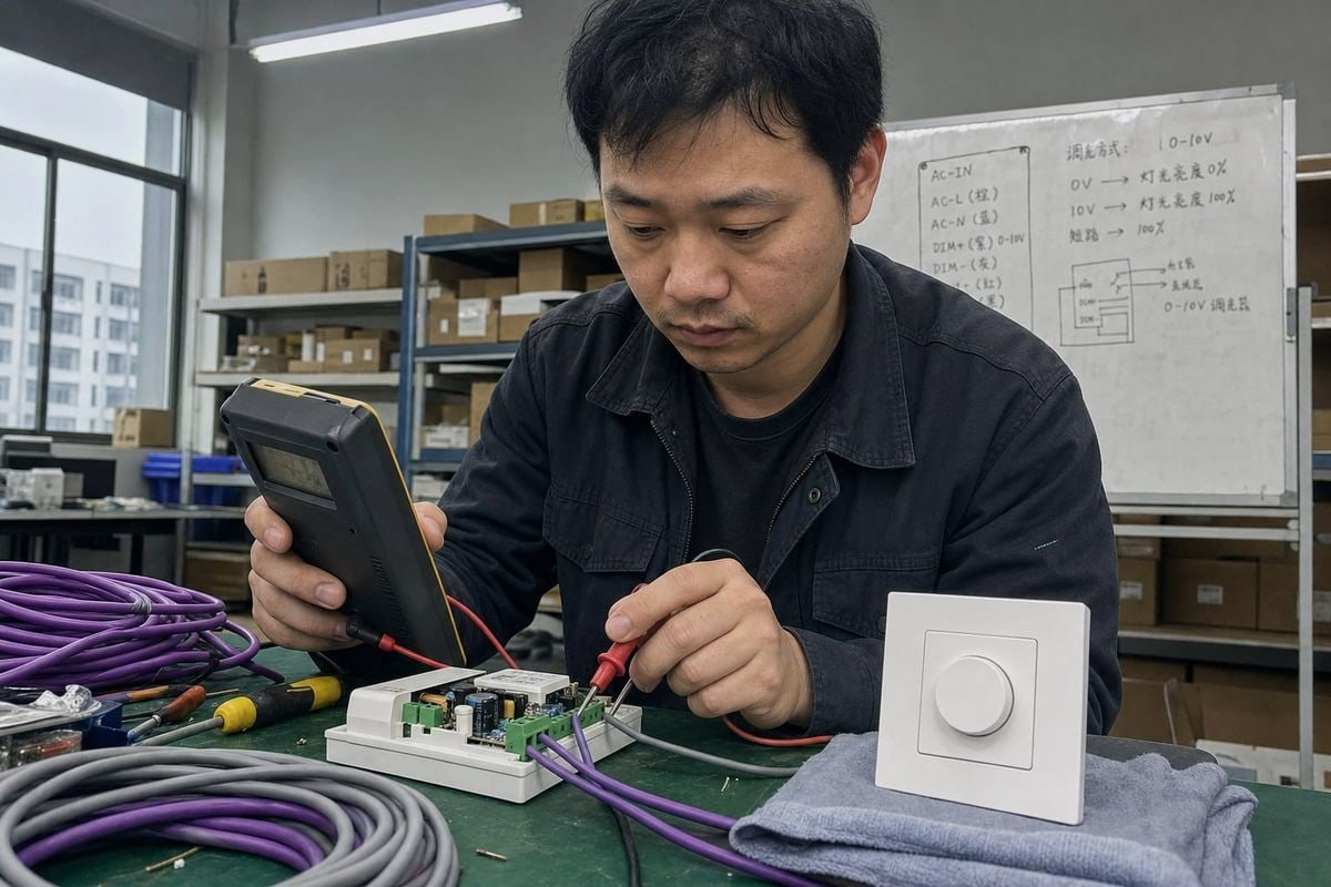
การควบคุมแสงแบบ 0–10V เป็นแบบแอนะล็อกหรือดิจิทัล? ฉันได้ยินคำถามนี้จากผู้ซื้อที่ประเมินไลน์ไดรเวอร์ LED ของเราอยู่ตลอดเวลา หากเข้าใจผิด โครงการทั้งหมดของคุณจะประสบปัญหาด้านประสิทธิภาพการควบคุมแสง.
การควบคุมแสงแบบ 0–10V เป็นวิธีการควบคุมแบบแอนะล็อก ไม่ใช่แบบดิจิทัล โดยใช้แรงดันไฟฟ้ากระแสตรงต่อเนื่องระหว่าง 0 ถึง 10 โวลต์เพื่อกำหนดระดับเอาต์พุตของไดรเวอร์ LED ต่างจาก DALI ที่ส่งคำสั่งดิจิทัลผ่านบัสสื่อสาร 0–10V แสดงความสว่างโดยตรงเป็นแรงดันไฟฟ้า.
นี่คือคำตอบสั้นๆ แต่ความสับสนเกี่ยวกับหัวข้อนี้มีจริง และทำให้บริษัทวิศวกรรมเสียเงินเมื่อระบุผลิตภัณฑ์ผิด ขออธิบายสิ่งที่สำคัญจริงๆ ให้ฟัง.
ฉันจะรู้ได้อย่างไรว่าระบบควบคุมแสงแบบ 0–10V ของฉันเป็นแบบแอนะล็อกหรือดิจิทัล?
ผู้ซื้อจากสิงคโปร์เคยส่งข้อความหาฉันทาง WhatsApp โดยเชื่อว่าระบบ 0–10V ของเขาเป็นแบบ “ดิจิทัล” เพราะคอนโทรลเลอร์อัจฉริยะมีแอป ฉันเข้าใจความสับสนได้ทันที — วิศวกรของเราเห็นสิ่งนี้ทุกสัปดาห์.
ระบบ 0–10V ของคุณเป็นแบบแอนะล็อก ระดับการควบคุมแสงเดินทางเป็นแรงดันไฟฟ้ากระแสตรงต่อเนื่องบนคู่สายควบคุมเฉพาะ โดยประมาณ 0V หมายถึงเอาต์พุตต่ำสุด และ 10V หมายถึงสูงสุด ไม่มีแพ็กเก็ตข้อมูลที่เข้ารหัส ไม่มีการระบุแอดเดรส และไม่มีผลตอบกลับแบบสองทางบนคู่สายนั้น.
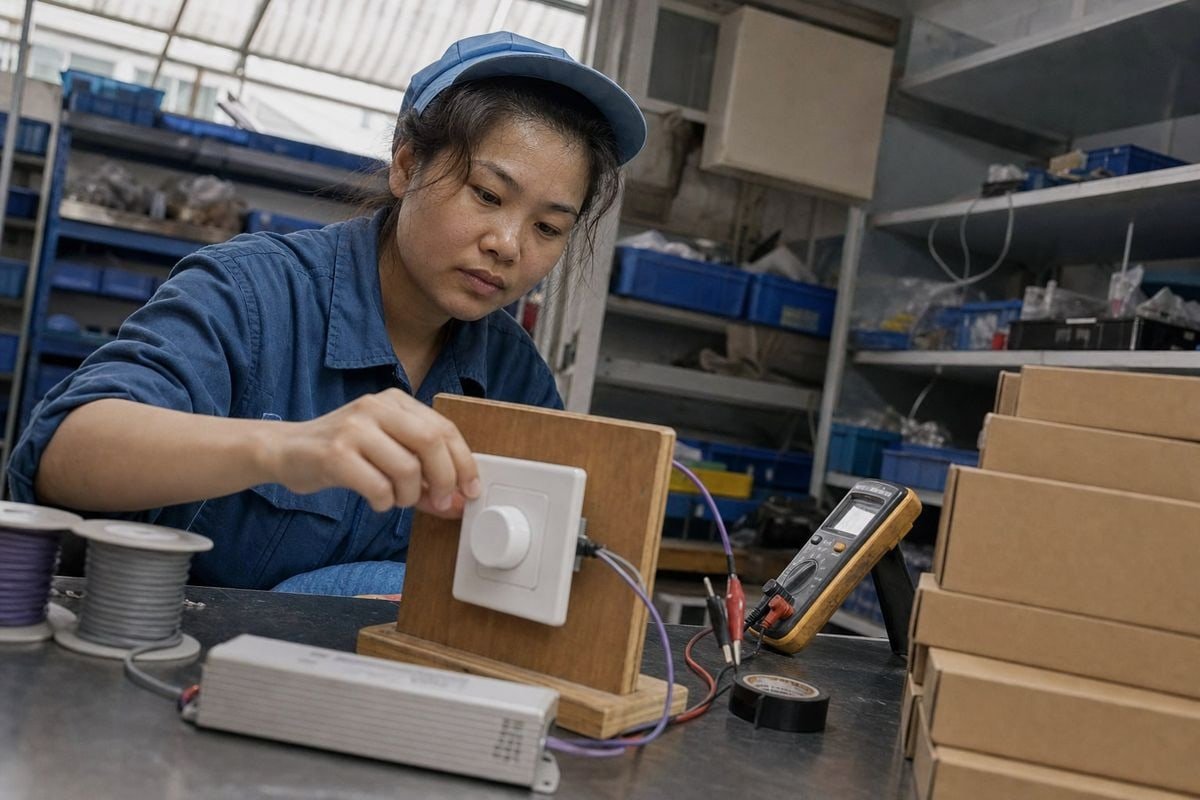
การทดสอบนั้นง่ายมาก วางมัลติมิเตอร์บนสายควบคุมสีม่วงและสีเทาขณะเลื่อนตัวควบคุมแสง หากเห็นแรงดันไฟฟ้ากระแสตรงที่เปลี่ยนแปลงอย่างราบรื่น แสดงว่ากำลังดูสัญญาณควบคุมแบบแอนะล็อก ระบบดิจิทัลเช่น ระบบควบคุม DALI 1 จะแสดงแรงดันบัสคงที่พร้อมพัลส์ข้อมูลซ้อนทับ ซึ่งมัลติมิเตอร์พื้นฐานไม่สามารถถอดรหัสได้.
นี่คือส่วนที่ทำให้คนสับสน. 0–10V เป็นแบบแอนะล็อกแม้ว่าตัวควบคุมเองจะถูกควบคุมแบบดิจิทัลก็ตาม. ก ระบบอาคารอัตโนมัติ 2 อาจรับคำสั่งดิจิทัลจากแพลตฟอร์มการจัดการ แล้วใช้อิเล็กทรอนิกส์สร้างเอาต์พุตแอนะล็อก 0–10V ระบบ อาจเป็นดิจิทัล แต่อินเทอร์เฟซระหว่างคอนโทรลเลอร์ 0–10V กับไดรเวอร์ LED ยังคงเป็นแอนะล็อก นี่คือสถานการณ์ที่ผู้ซื้อจากสิงคโปร์ของฉันเจอ.
สายสัญญาณภายในไดรเวอร์
มีอีกชั้นหนึ่งที่ควรรู้ สำหรับ ไดรเวอร์ LED แรงดันคงที่, สายสัญญาณที่ใช้งานได้จริงโดยทั่วไปคือ:
สัญญาณควบคุม 0–10V → ไดรเวอร์ LED → การควบคุม PWM/กระแส → โหลด LED
ดังนั้นไดรเวอร์สมัยใหม่มักทำหน้าที่เป็นอุปกรณ์ไฮบริด พวกเขาสุ่มตัวอย่างแรงดันแอนะล็อกและสร้าง การมอดูเลตความกว้างพัลส์ 3 เอาต์พุตเพื่อการควบคุมแสงที่ราบรื่นและไม่กระพริบ ด้านอินพุตยังคงเป็นแอนะล็อก ด้านเอาต์พุตอาจเป็น PWM พฤติกรรมไฮบริดนี้ไม่ได้ทำให้วิธีการควบคุมเป็นดิจิทัล คำถามที่ชี้ขาดคือสิ่งที่เดินทางบนสายควบคุม — และที่นี่ มันคือระดับแรงดันไฟฟ้าธรรมดา ไม่ใช่ข้อความที่เข้ารหัส.
รายการตรวจสอบการระบุอย่างรวดเร็ว
| สิ่งที่คุณสังเกตเห็น | ความหมาย |
|---|---|
| แรงดันไฟฟ้ากระแสตรงที่เปลี่ยนแปลงอย่างราบรื่น (0–10V) บนคู่สายควบคุม | การควบคุมแสงแบบแอนะล็อก 0–10V |
| แรงดันบัสคงที่พร้อมพัลส์ข้อมูล (ประมาณ 16V) | บัส DALI แบบดิจิทัล |
| เอกสารข้อมูลไดรเวอร์ระบุ “current sinking, 1–10V” | แอนะล็อก, รูปแบบตามมาตรฐาน IEC 60929 4ไฟทั้งหมดบนคู่สายหนึ่งควบคุมพร้อมกัน ไม่มีการระบุแอดเดรสรายบุคคล |
| พฤติกรรมการกระจายสัญญาณแบบแอนะล็อก | 0–10V ยังคงเป็นอินเทอร์เฟซแอนะล็อกแม้ขับเคลื่อนโดยคอนโทรลเลอร์อัจฉริยะแบบดิจิทัล |
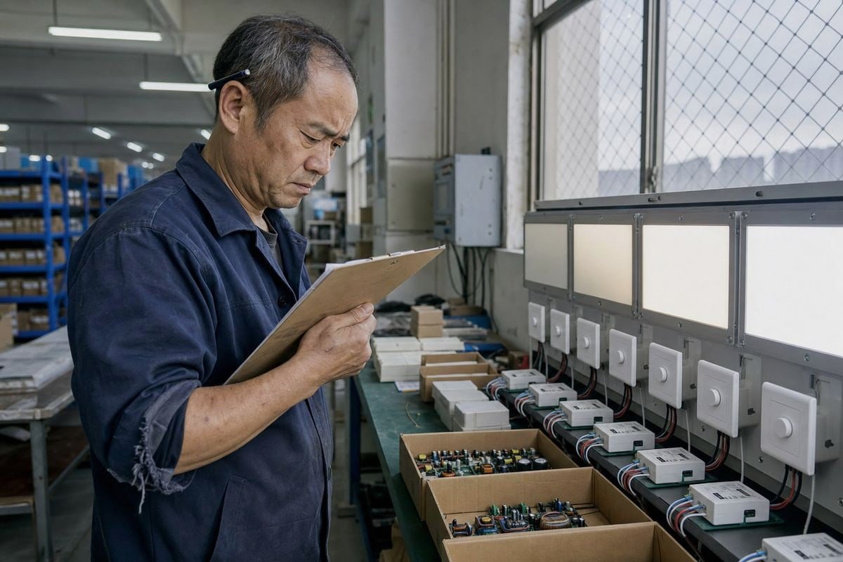
ระหว่างการตรวจสอบคุณภาพเป็นชุดที่โรงงานของเราเมื่อปีที่แล้ว เราปฏิเสธตัวอย่างคู่แข่งที่ลูกค้าส่งมาเพื่อการเปรียบเทียบ เส้นโค้งการควบคุมแสงไม่สม่ำเสมอมากจนเอาต์พุตกระโดดอย่างเห็นได้ชัดระหว่าง 20% และ 30% ข้อบกพร่องเพียงจุดเดียวจะทำลายโครงการโรงแรมของเขา
ขออธิบายแต่ละจุด เพราะแต่ละจุดแสดงออกแตกต่างกันในภาคสนาม.
ระวังปัญหาสี่ประการ: อินเทอร์เฟซแบบซิงก์และซอร์สที่ไม่ตรงกัน, เส้นโค้งการหรี่แสงที่ไม่เป็นเชิงเส้นหรือไม่สม่ำเสมอ, การกะพริบที่ระดับเอาต์พุตต่ำ, และกระแสรั่วสะสมบนวงจรความหนาแน่นสูงที่ป้องกันไม่ให้แรงดันไฟฟ้าลดลงต่ำพอที่จะกระตุ้นการหรี่จนปิด.
ความไม่ตรงกันระหว่างแบบซิงก์และแบบซอร์ส.
นี่คือกับดักการจัดหาอันดับหนึ่ง จริงๆ แล้วมี
มาตรฐาน 0–10V ที่พบได้ทั่วไปสองแบบ และคำอธิบายออนไลน์หลายแห่งทำให้ทั้งสองปนกัน:, ประเภท
| Type | ฟังก์ชันทั่วไป | การใช้งานทั่วไป |
|---|---|---|
| ควบคุมด้วยแหล่งจ่าย 0–10V | ตัวควบคุม แหล่งจ่าย แรงดันควบคุม; ไดรเวอร์ตรวจจับมัน | ระบบโรงละครและระบบสถาปัตยกรรมบางระบบ |
| แบบ 1–10V / ตามมาตรฐาน IEC 60929 | ไดรเวอร์จ่ายกระแสควบคุมและตัวควบคุม ดูดซับ มัน; 1V มักเป็นระดับควบคุมขั้นต่ำ | ไฟสถาปัตยกรรม, ไดรเวอร์ LED ส่วนใหญ่ |
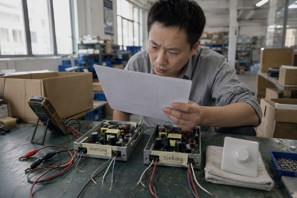
ดังนั้น “0–10V” ไม่ควรถูกมองว่าเหมือนกับ “1–10V” โดยอัตโนมัติ ก่อนที่เราจะจัดส่งดิimmerหรือไดรเวอร์ใดๆ เรายืนยันว่าระบบของผู้ซื้อคาดหวังการดูดซับกระแสหรือการจ่ายกระแส การผสมกันหมายความว่าดิimmerจะไม่ทำงานเลย และเราเคยเห็นตัวแทนจำหน่ายส่งคืนทั้งชุดสินค้าเพราะเหตุนี้.
เส้นโค้งการลดแสงและการกะพริบ
ถามซัพพลายเออร์ของคุณสำหรับข้อกำหนดเส้นโค้งการลดแสง — แบบเส้นตรงหรือลอการิทึม — และทดสอบตัวอย่างที่เอาต์พุต 10%, 5% และ 1% ไดรเวอร์ราคาถูกมัก กะพริบอย่างรุนแรงต่ำกว่า 10% เพราะความถี่ Pulse Width Modulation ภายในต่ำเกินไป บนสายการผลิตของเรา เราทดสอบทุกชุดไดรเวอร์แบบลดแสงได้ตลอดช่วงก่อนบรรจุ เพราะลูกค้าวิศวกรของเราในเยอรมนีและออสเตรเลียจะวัดด้วยตัวเอง.
กระแสรั่วไหลบนวงจรหนาแน่น
นี่คือจุดที่ละเอียดอ่อน วงจร 0–10V ความหนาแน่นสูงสามารถประสบปัญหากระแสรั่วไหลสะสมจากไดรเวอร์หลายตัว การรั่วไหลนั้นอาจป้องกันไม่ให้แรงดันควบคุมลดลงต่ำพอที่จะถึงสถานะปิดสนิท หากโครงการของคุณมีไดรเวอร์สี่สิบตัวบนคู่ควบคุมเดียว ให้ตรวจสอบข้อกำหนดการรั่วไหลของแต่ละไดรเวอร์และความสามารถในการดูดซับของดิimmer นอกจากนี้ ควรคำนึงถึงแรงดันตกบนสายควบคุมระยะยาว ซึ่งทำให้ระดับการลดแสงจริงเบี่ยงเบนไปจากที่ตัวควบคุมสั่ง.
ฉันต้องตรวจสอบใบรับรองใดบ้างสำหรับความเข้ากันได้ของการลดแสง 0–10V ในโครงการของฉัน?
คำถามเกี่ยวกับการปฏิบัติตามข้อกำหนดเกิดขึ้นในเกือบทุกใบเสนอราคาที่เราเตรียมสำหรับลูกค้าในยุโรปและเอเชีย ตัวแทนจำหน่ายไฟในอิตาลีเคยเลื่อนคำสั่งซื้อสามสัปดาห์เพียงเพื่อตรวจสอบเครื่องหมายหนึ่งซ้ำ — ความล่าช้าที่เอกสารที่เหมาะสมจะหลีกเลี่ยงได้.
ตรวจสอบใบรับรองความปลอดภัยที่ตรงกับตลาดของคุณ (CE, UKCA หรือเทียบเท่าระดับภูมิภาค), การปฏิบัติตาม EMC สำหรับความสมบูรณ์ของสัญญาณควบคุม, การปฏิบัติตาม IEC 60929 สำหรับอินเทอร์เฟซ 1–10V และการปฏิบัติตามการเดินสาย Class 2 สำหรับคู่ควบคุมแรงดันต่ำ รวมถึงกฎสีสายไฟ NEC 2020 สำหรับโครงการในอเมริกาเหนือ.
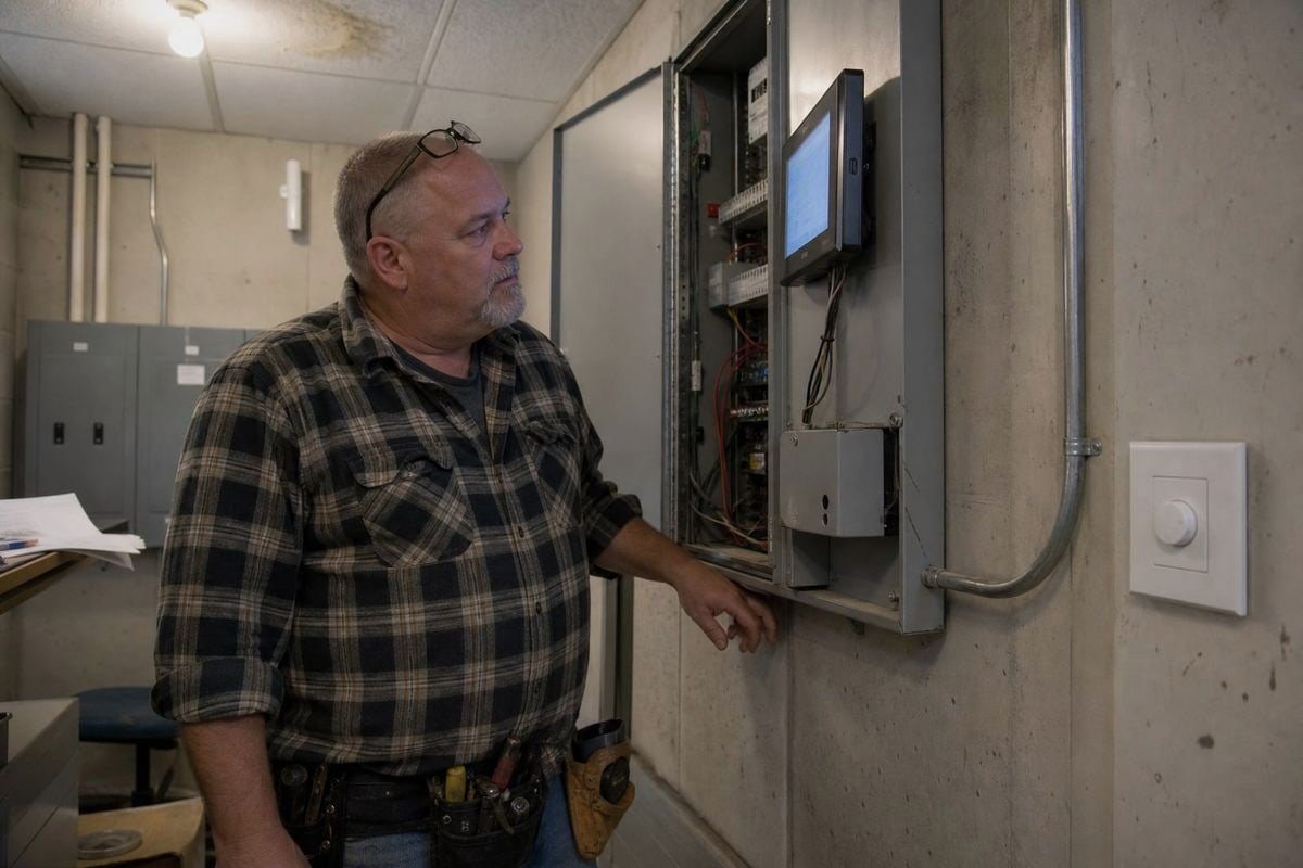
ใบรับรองไม่ใช่แค่เอกสาร พวกเขาบอกคุณว่าไดรเวอร์และดิimmerจะทำงานอย่างคาดเดาได้เมื่อติดตั้งหรือไม่ จากประสบการณ์ของเราในการส่งออกไปญี่ปุ่น อิตาลี ฝรั่งเศส อังกฤษ เยอรมนี และทั่วเอเชียตะวันออกเฉียงใต้ แต่ละตลาดมีรายการตรวจสอบของตัวเอง และการข้ามหนึ่งรายการทำให้ศุลกากรติดขัดหรือการตรวจสอบไซต์ล้มเหลว.
รายการตรวจสอบหลักตามหมวดหมู่
| หมวดหมู่ | สิ่งที่ต้องตรวจสอบ | เหตุใดจึงสำคัญสำหรับ 0–10V |
|---|---|---|
| ความปลอดภัย | CE, UKCA หรือเครื่องหมายของประเทศปลายทาง | การเข้าถึงตลาดตามกฎหมายและความปลอดภัยทางไฟฟ้าพื้นฐาน |
| อีเอ็มซี | การปฏิบัติตามการปล่อยและการป้องกันสัญญาณรบกวน | ป้องกันการรบกวนสัญญาณควบคุมบนคู่ 0–10V |
| มาตรฐานอินเทอร์เฟซ | IEC 60929 สำหรับไดรเวอร์แบบดูดซับ 1–10V | ยืนยันว่าอินเทอร์เฟซการลดแสงทำงานตามที่ระบุ |
| การเดินสายแรงดันต่ำ | การปฏิบัติตามการเดินสาย Class 2 | อนุญาตให้คู่ควบคุมทำงานด้วยกฎการติดตั้งที่ง่ายขึ้น |
| การระบุสายไฟ | การอัปเดตสี NEC 2020 (โครงการในสหรัฐฯ) | สีตัวนำที่ถูกต้องระหว่างการตรวจสอบ |
รายละเอียด NEC 2020 ที่ผู้ซื้อส่วนใหญ่พลาด
การติดตั้งมาตรฐานในอดีตใช้สีม่วงสำหรับสายควบคุมบวกและสีเทาสำหรับสายลบ แต่ NEC 2020 กำหนดให้เปลี่ยนจากสีเทาเป็นสีชมพูสำหรับสายควบคุมลบ เหตุผลคือความปลอดภัย: สีเทาอาจสับสนกับตัวนำกลางที่ต่อลงดิน หากโครงการของคุณอยู่ในอเมริกาเหนือ ให้ตรวจสอบว่าสายไฟหรือเอกสารของซัพพลายเออร์สะท้อนการเปลี่ยนแปลงนี้ เราอัปเดตเอกสารส่งออกของเราในปีที่กฎนี้มีผล และมันช่วยลูกค้าหลายรายจากการถูกธงในการตรวจสอบ.
EMC และความสมบูรณ์ของสัญญาณ
พื้นที่ใบรับรองหนึ่งที่ผู้ซื้อประเมินต่ำเกินไปคือ EMC คู่ 0–10V เป็นแรงดันต่ำ และเมื่อเดินสายยาว มีความเสี่ยงต่อการรบกวนสัญญาณควบคุมจากตัวนำไฟฟ้าใกล้เคียง ไดรเวอร์ที่มีการออกแบบ EMC ที่ดีจะกรองสัญญาณรบกวนนั้น ไดรเวอร์ที่ออกแบบไม่ดีจะทำให้ระดับการลดแสงลอยหรือกะพริบ ขอรายงานการทดสอบ EMC ไม่ใช่แค่โลโก้บนฉลาก ซัพพลายเออร์ที่น่าเชื่อถือจะส่งให้โดยไม่ลังเล — และที่ boqi ทีมสนับสนุนเทคนิคของเราจะพาลูกค้าดูรายงานเมื่อจำเป็น.

ฉันจะเลือกระหว่างการหรี่แสงแบบแอนะล็อก 0–10V และดิจิทัล DALI สำหรับโปรเจกต์วิศวกรรมของฉันได้อย่างไร?
เนื่องจากเราผลิตทั้งไดรเวอร์แบบหรี่แสงได้ DALI และไดรเวอร์แบบหรี่แสงได้ 0–10V ฉันจึงไม่มีผลประโยชน์ที่จะผลักดันให้เลือกแบบใดแบบหนึ่ง คำตอบที่ตรงไปตรงมาขึ้นอยู่กับโปรเจกต์ — และฉันเคยพูดโน้มน้าวลูกค้ามากกว่าหนึ่งรายให้เลิกใช้ตัวเลือกที่แพงกว่า.
เลือก 0–10V สำหรับการหรี่แสงแบบโซนที่เรียบง่ายและคุ้มค่า ซึ่งโคมไฟทั้งหมดบนคู่สายหนึ่งหรี่พร้อมกัน เลือก DALI เมื่อคุณต้องการระบุที่อยู่โคมไฟรายดวง การตอบกลับสถานะแบบสองทาง คำสั่งฉากดิจิทัล หรือการเชื่อมต่อกับระบบอาคารอัตโนมัติ.
นี่คือมุมมองแบบเทียบเคียงที่ฉันร่างให้ลูกค้าก่อนที่เราจะเสนอราคาอะไรก็ตาม:
| ปัจจัย | แอนะล็อก 0–10V | DALI ดิจิทัล |
|---|---|---|
| ประเภทสัญญาณ | แรงดันไฟฟ้ากระแสตรงต่อเนื่อง | คำสั่งดิจิทัลที่เข้ารหัสบนบัส |
| การระบุที่อยู่ | ไม่มี — โคมไฟทั้งหมดบนคู่สายหรี่พร้อมกัน | การระบุที่อยู่รายดวงและรายกลุ่ม |
| การตอบกลับ | ทิศทางเดียว ไม่มีการตรวจสอบสถานะ | สองทาง; ไดรเวอร์รายงานข้อผิดพลาดและสถานะ |
| ฉาก | ไม่ผ่านคู่สายหรี่แสงเอง | คำสั่งฉากดิจิทัลที่สร้างไว้ในโปรโตคอล |
| การเดินสายไฟ | คู่สายควบคุมที่ไวต่อขั้ว | บัสสองสายที่ไม่ไวต่อขั้ว |
| ต้นทุน | ต่ำกว่าต่อจุด | สูงกว่า แต่มีความสามารถมากกว่าต่อจุด |
| การติดตั้งและตั้งค่า | เสียบแล้วหรี่ได้ | ต้องมีการระบุที่อยู่และการกำหนดค่า |
เมื่อ 0–10V ชนะ
คลังสินค้า โกดังสูง แผงไฟ ลานจอดรถ — ทุกที่ที่หนึ่งโซนหรี่เป็นบล็อก ระบบนี้เรียบง่าย ทนทาน และราคาถูกในการติดตั้ง ผู้รับเหมาเข้าใจอยู่แล้ว และ 0–10V กำลังพัฒนา: แอปพลิเคชันไวท์ปรับได้ขั้นสูงตอนนี้ใช้ช่องสัญญาณ 0–10V แบบคู่ หนึ่งช่องสำหรับความเข้มและหนึ่งช่องสำหรับอุณหภูมิสี ทั้งหมดผ่านสัญญาณแอนะล็อก แอนะล็อกไม่ได้หมายความว่าล้าสมัย.
เมื่อ DALI ชนะ
สำนักงาน โรงพยาบาล โรงแรม และทุกไซต์ที่เชื่อมต่อกับระบบอาคารอัตโนมัติ DALI เป็นดิจิทัลและระบุที่อยู่ได้ ดังนั้นคุณสามารถจัดกลุ่มโคมไฟใหม่ในซอฟต์แวร์แทนการเดินสายใหม่ กำหนดเวลาฉาก และรับรายงานข้อผิดพลาดจากไดรเวอร์ LED แต่ละตัว ในโปรเจกต์สำนักงานห้าร้อยโคม ความยืดหยุ่นนั้นมักจะคุ้มค่ากับค่าใช้จ่าย.
ความเป็นจริงแบบไฮบริด
ลูกค้าวิศวกรหลายรายของเราผสมทั้งสองแบบ พวกเขาใช้ DALI ในชั้นสำนักงานและ 0–10V ในพื้นที่ส่วนหลังของอาคาร เนื่องจากเราผลิตไดรเวอร์ทั้งสองประเภทพร้อมกับคอนโทรลเลอร์ DALI และตัวหรี่ 0–10V ที่เข้ากัน เราจึงมักจัดหาทั้งสองแบบให้กับโปรเจกต์เดียว — และเราทำให้แน่ใจว่าข้อกำหนดสำหรับแต่ละโซนถูกกำหนดไว้ก่อนเริ่มการผลิต คำตอบสั้นๆ อย่างที่ฉันบอกลูกค้าใหม่ทุกคน: 0–10V = การควบคุมแอนะล็อก DALI = การควบคุมดิจิทัล. เลือกตามความฉลาดที่แต่ละพื้นที่ต้องการจริงๆ.
บทสรุป
การหรี่แสง 0–10V เป็นแอนะล็อก: แรงดันไฟฟ้าต่อเนื่องกำหนดความสว่าง ในขณะที่ DALI ส่งคำสั่งดิจิทัล ตรวจสอบการจมกับแหล่งจ่าย การรับรอง และกฎการเดินสาย — จากนั้นเลือกวิธีการควบคุมที่โปรเจกต์ของคุณต้องการจริงๆ.
เชิงอรรถ
- พันธมิตรอุตสาหกรรมอย่างเป็นทางการสำหรับ DALI ให้ข้อกำหนดทางเทคนิคสำหรับการควบคุมแสงดิจิทัล. ↩︎
- แหล่งข้อมูลของกระทรวงพลังงานสหรัฐฯ เกี่ยวกับระบบอาคารและเทคโนโลยีอัตโนมัติ. ↩︎
- คำอธิบายทางเทคนิคของเทคนิคเอาต์พุตภายในที่ใช้โดยไดรเวอร์ LED สำหรับการหรี่แสง. ↩︎
- มาตรฐานสากลที่กำหนดอินเทอร์เฟซการหรี่แสงแอนะล็อก 1-10V สำหรับบัลลาสต์อิเล็กทรอนิกส์. ↩︎