Chuyển đến nội dung










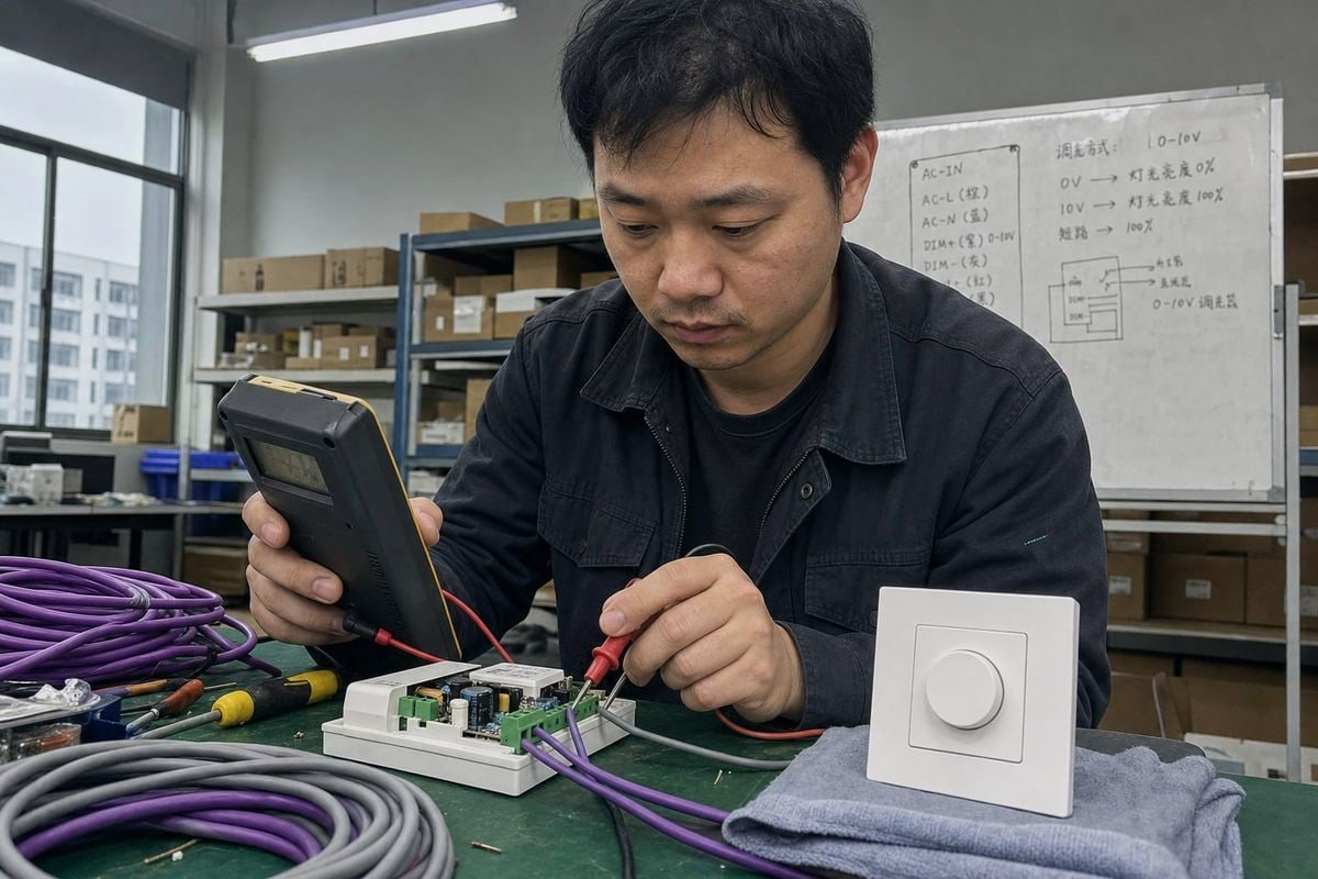
Điều chỉnh độ sáng 0–10V là analog hay digital? Tôi nghe câu hỏi này liên tục từ người mua khi họ đánh giá dòng driver LED của chúng tôi. Nếu hiểu sai, toàn bộ hiệu suất điều chỉnh độ sáng của dự án bạn sẽ bị ảnh hưởng.
Điều chỉnh độ sáng 0–10V là một phương pháp điều khiển analog, không phải digital. Nó sử dụng điện áp DC liên tục từ 0 đến 10 volt để thiết lập mức đầu ra của driver LED. Khác với DALI, vốn gửi lệnh digital qua bus truyền thông, 0–10V biểu thị độ sáng trực tiếp dưới dạng điện áp.
Đó là câu trả lời ngắn gọn. Nhưng sự nhầm lẫn xung quanh chủ đề này là có thật, và nó khiến các công ty kỹ thuật tốn kém chi phí khi chọn sai sản phẩm. Hãy để tôi giải thích những gì thực sự quan trọng.
Làm sao tôi biết hệ thống điều chỉnh độ sáng 0–10V của mình là analog hay digital?
Một người mua từ Singapore từng nhắn tin cho tôi trên WhatsApp, tin rằng hệ thống 0–10V của anh ấy là “digital” vì bộ điều khiển thông minh của anh ấy có ứng dụng. Tôi hiểu ngay sự nhầm lẫn này — các kỹ sư của chúng tôi thấy điều đó hàng tuần.
Hệ thống 0–10V của bạn là analog. Mức độ sáng được truyền dưới dạng điện áp DC liên tục trên một cặp dây điều khiển riêng, trong đó khoảng 0V nghĩa là đầu ra tối thiểu và 10V nghĩa là tối đa. Không có gói dữ liệu mã hóa, không có địa chỉ, và không có phản hồi hai chiều trên cặp dây đó.
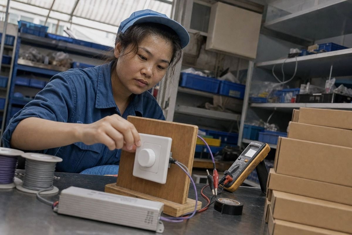
Cách kiểm tra rất đơn giản. Đặt đồng hồ vạn năng lên dây điều khiển màu tím và xám trong khi bạn di chuyển bộ điều chỉnh độ sáng. Nếu bạn thấy điện áp DC thay đổi mượt mà, bạn đang nhìn thấy tín hiệu điều khiển analog. Một hệ thống digital như hệ thống điều khiển DALI 1 sẽ hiển thị điện áp bus cố định với các xung dữ liệu chồng lên, mà đồng hồ cơ bản không thể giải mã được.
Đây là phần khiến mọi người bối rối. 0–10V là analog ngay cả khi bộ điều khiển chính nó được điều khiển bằng digital. MỘT hệ thống tự động hóa tòa nhà 2 có thể nhận lệnh digital từ nền tảng quản lý và sau đó sử dụng điện tử để tạo ra đầu ra analog 0–10V. hệ thống có thể là digital, nhưng giao diện giữa bộ điều khiển 0–10V và driver LED vẫn là analog. Đây chính xác là tình huống mà người mua Singapore của tôi gặp phải.
Chuỗi tín hiệu bên trong driver
Có thêm một lớp nữa đáng để biết. Đối với driver LED điện áp không đổi, chuỗi tín hiệu thực tế thường là:
Tín hiệu điều khiển 0–10V → driver LED → điều khiển PWM/dòng điện → tải LED
Vì vậy, các driver hiện đại thường hoạt động như thiết bị lai. Chúng lấy mẫu điện áp analog và bên trong tạo ra đầu ra Điều chế độ rộng xung 3 để làm mờ mượt mà, không nhấp nháy. Phía đầu vào vẫn là analog; phía đầu ra có thể là PWM. Hành vi lai đó không làm cho phương pháp điều khiển trở thành digital. Câu hỏi quyết định là những gì truyền trên dây điều khiển — và ở đây, đó là mức điện áp đơn giản, không phải thông điệp mã hóa.
Danh sách kiểm tra nhận dạng nhanh
| Điều bạn quan sát | Ý nghĩa |
|---|---|
| Điện áp DC thay đổi mượt mà (0–10V) trên cặp dây điều khiển | Điều chỉnh độ sáng 0–10V analog |
| Điện áp bus cố định với xung dữ liệu (khoảng 16V) | Bus DALI digital |
| Bảng dữ liệu driver ghi “hút dòng, 1–10V” | Biến thể analog, kiểu IEC 60929 4Tất cả đèn trên một cặp dây mờ cùng nhau, không có địa chỉ riêng lẻ |
| Hành vi phát sóng analog | 0–10V vẫn là giao diện analog ngay cả khi được điều khiển bởi bộ điều khiển thông minh digital |
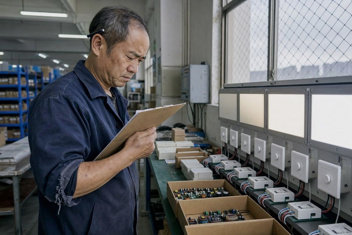
Trong một đợt kiểm tra QC hàng loạt tại nhà máy của chúng tôi năm ngoái, chúng tôi đã từ chối một mẫu sản phẩm của đối thủ mà khách hàng gửi để đánh giá so sánh. Đường cong điều chỉnh độ sáng không đều đến mức đầu ra nhảy thấy rõ giữa 20% và 30%. Chỉ riêng lỗi đó đã có thể phá hỏng dự án khách sạn của anh ấy.
Hãy để tôi phân tích từng vấn đề, vì mỗi vấn đề xuất hiện khác nhau trên thực tế.
Hãy chú ý đến bốn vấn đề: giao diện sinking và sourcing không khớp nhau, đường cong điều chỉnh độ sáng phi tuyến hoặc không nhất quán, nhấp nháy ở mức công suất thấp, và dòng rò tích lũy trên các mạch mật độ cao khiến điện áp không thể giảm đủ thấp để kích hoạt chế độ tắt dần.
Sự không khớp giữa hút dòng và cấp dòng.
Đây là cái bẫy số một khi tìm nguồn cung. Thực tế có
hai tiêu chuẩn 0–10V thường gặp , và nhiều giải thích trực tuyến làm mờ ranh giới giữa chúng:, Loại
| Type | Chức năng điển hình | Ứng dụng phổ biến |
|---|---|---|
| Điều khiển bằng nguồn 0–10V | Bộ điều khiển cấp nguồn điện áp điều khiển; driver cảm nhận nó | Hệ thống sân khấu và một số hệ thống kiến trúc |
| Kiểu 1–10V / IEC 60929 | Driver cung cấp dòng điều khiển và bộ điều khiển hút dòng đó; 1V thường là mức điều khiển tối thiểu | Chiếu sáng kiến trúc, hầu hết driver LED |
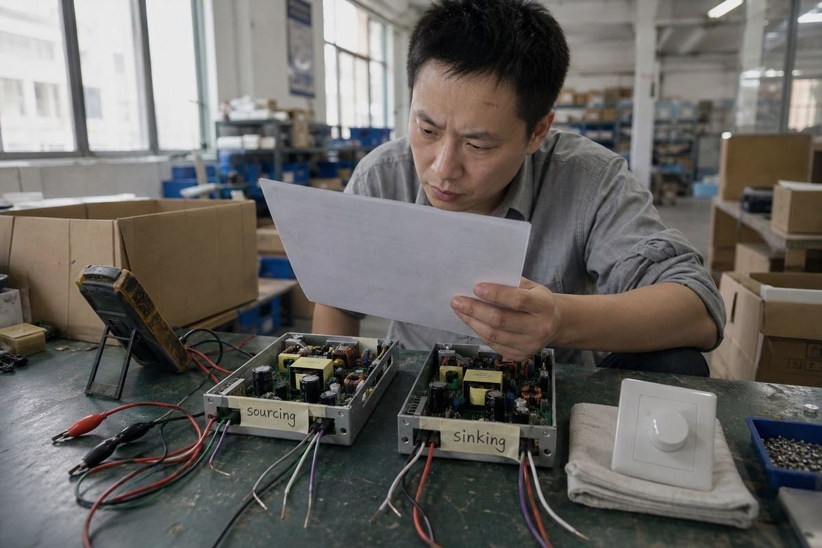
Vì vậy, “0–10V” không nên tự động được coi là giống với “1–10V.” Trước khi chúng tôi xuất xưởng bất kỳ bộ điều chỉnh độ sáng hoặc driver nào, chúng tôi xác nhận xem hệ thống của người mua mong đợi hút dòng hay cấp dòng. Trộn lẫn chúng có nghĩa là bộ điều chỉnh độ sáng sẽ không hoạt động, và chúng tôi đã thấy các nhà phân phối trả lại toàn bộ lô hàng vì điều này.
Đường cong điều chỉnh độ sáng và nhấp nháy
Hỏi nhà cung cấp của bạn về thông số kỹ thuật đường cong điều chỉnh độ sáng — tuyến tính hoặc logarit — và kiểm tra mẫu ở mức đầu ra 10%, 5% và 1%. Driver giá rẻ thường nhấp nháy nghiêm trọng dưới 10% vì tần số Điều chế độ rộng xung bên trong của chúng quá thấp. Trên dây chuyền sản xuất của chúng tôi, chúng tôi kiểm tra mọi lô driver điều chỉnh độ sáng trên toàn dải trước khi đóng gói, vì khách hàng kỹ thuật của chúng tôi ở Đức và Úc sẽ tự đo lường.
Dòng rò trên mạch mật độ cao
Đây là một điểm tinh tế. Mạch 0–10V mật độ cao có thể bị ảnh hưởng bởi dòng rò tích lũy trên nhiều driver. Dòng rò đó có thể ngăn điện áp điều khiển giảm đủ thấp để đạt trạng thái tắt khi điều chỉnh độ sáng. Nếu dự án của bạn có bốn mươi driver trên một cặp điều khiển, hãy kiểm tra thông số dòng rò của từng driver và khả năng hút của bộ điều chỉnh độ sáng. Cũng tính đến sụt áp trên đường điều khiển dài, làm thay đổi mức điều chỉnh độ sáng thực tế so với lệnh của bộ điều khiển.
Tôi cần xác minh những chứng nhận nào để tương thích điều chỉnh độ sáng 0–10V trong các dự án của mình?
Các câu hỏi về tuân thủ xuất hiện trong gần như mọi báo giá chúng tôi chuẩn bị cho khách hàng châu Âu và châu Á. Một nhà phân phối chiếu sáng ở Ý từng trì hoãn đơn hàng ba tuần chỉ để kiểm tra lại một dấu hiệu — một sự chậm trễ mà tài liệu đúng đắn có thể tránh được.
Xác minh chứng nhận an toàn phù hợp với thị trường của bạn (CE, UKCA hoặc tương đương khu vực), tuân thủ EMC cho tính toàn vẹn tín hiệu điều khiển, tuân thủ IEC 60929 cho giao diện 1–10V và tuân thủ hệ thống dây Class 2 cho cặp điều khiển điện áp thấp, bao gồm quy tắc màu dây NEC 2020 cho các dự án Bắc Mỹ.
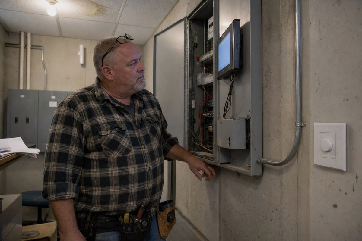
Chứng nhận không chỉ là giấy tờ. Chúng cho bạn biết liệu driver và bộ điều chỉnh độ sáng có hoạt động dự đoán được khi lắp đặt hay không. Theo kinh nghiệm xuất khẩu của chúng tôi đến Nhật Bản, Ý, Pháp, Anh, Đức và khắp Đông Nam Á, mỗi thị trường có danh sách kiểm tra riêng, và bỏ qua một mục sẽ làm kẹt hải quan hoặc thất bại kiểm tra tại hiện trường.
Danh sách kiểm tra cốt lõi theo danh mục
| Danh mục | Điều cần xác minh | Tại sao quan trọng cho 0–10V |
|---|---|---|
| An toàn | CE, UKCA hoặc dấu hiệu của quốc gia đích | Tiếp cận thị trường hợp pháp và an toàn điện cơ bản |
| EMC | Tuân thủ phát xạ và miễn nhiễm | Ngăn nhiễu tín hiệu điều khiển trên cặp 0–10V |
| Tiêu chuẩn giao diện | IEC 60929 cho driver loại hút dòng 1–10V | Xác nhận giao diện điều chỉnh độ sáng hoạt động như tài liệu mô tả |
| Hệ thống dây điện áp thấp | Tuân thủ hệ thống dây Class 2 | Cho phép cặp điều khiển chạy với quy tắc lắp đặt đơn giản hơn |
| Nhận dạng dây | Cập nhật màu sắc NEC 2020 (dự án Hoa Kỳ) | Màu dây dẫn chính xác trong quá trình kiểm tra |
Chi tiết NEC 2020 mà hầu hết người mua bỏ lỡ
Các lắp đặt tiêu chuẩn trước đây sử dụng màu tím cho dây điều khiển dương và màu xám cho dây âm. Nhưng NEC 2020 yêu cầu chuyển từ màu xám sang màu hồng cho dây điều khiển âm. Lý do là an toàn: màu xám có thể bị nhầm với dây trung tính nối đất. Nếu dự án của bạn ở Bắc Mỹ, hãy xác minh rằng dây dẫn hoặc tài liệu của nhà cung cấp phản ánh thay đổi này. Chúng tôi đã cập nhật tài liệu xuất khẩu vào năm quy tắc này được ban hành, và điều đó đã cứu một số khách hàng khỏi cờ đỏ kiểm tra.
EMC và tính toàn vẹn tín hiệu
Một lĩnh vực chứng nhận mà người mua đánh giá thấp là EMC. Cặp 0–10V là điện áp thấp và, trên đường chạy dài, dễ bị nhiễu tín hiệu điều khiển từ các dây dẫn điện gần đó. Một driver có thiết kế EMC tốt sẽ lọc nhiễu đó; một driver thiết kế kém sẽ làm mức điều chỉnh độ sáng trôi hoặc nhấp nháy. Hãy yêu cầu báo cáo kiểm tra EMC, không chỉ logo trên nhãn. Nhà cung cấp uy tín sẽ đưa ra mà không do dự — và tại boqi, đội ngũ hỗ trợ kỹ thuật của chúng tôi hướng dẫn khách hàng qua các báo cáo khi cần.

Làm thế nào để tôi chọn giữa điều chỉnh độ sáng analog 0–10V và DALI kỹ thuật số cho các dự án kỹ thuật của mình?
Vì chúng tôi sản xuất cả bộ điều khiển có thể điều chỉnh độ sáng DALI và bộ điều khiển có thể điều chỉnh độ sáng 0–10V, tôi không có ý định ủng hộ cái nào hơn cái nào. Câu trả lời trung thực phụ thuộc vào dự án — và tôi đã khuyên nhiều hơn một khách hàng từ bỏ lựa chọn đắt tiền hơn.
Chọn 0–10V cho việc điều chỉnh độ sáng theo vùng đơn giản, tiết kiệm chi phí khi tất cả các đèn trên một cặp dây điều chỉnh cùng nhau. Chọn DALI khi bạn cần định địa chỉ từng bộ đèn, phản hồi trạng thái hai chiều, lệnh cảnh kỹ thuật số, hoặc tích hợp với hệ thống tự động hóa tòa nhà.
Đây là cái nhìn so sánh cạnh nhau mà tôi phác thảo cho khách hàng trước khi chúng tôi báo giá bất cứ điều gì:
| Yếu tố | Analog 0–10V | DALI kỹ thuật số |
|---|---|---|
| Loại tín hiệu | Điện áp DC liên tục | Lệnh kỹ thuật số được mã hóa trên bus |
| Định địa chỉ | Không có — tất cả các đèn trên cặp dây điều chỉnh cùng nhau | Định địa chỉ cá nhân và nhóm |
| Phản hồi | Một chiều, không có giám sát trạng thái | Hai chiều; bộ điều khiển báo cáo lỗi và trạng thái |
| Cảnh | Không thông qua chính cặp điều chỉnh độ sáng | Lệnh cảnh kỹ thuật số được tích hợp trong giao thức |
| Hệ thống dây điện | Cặp điều khiển nhạy cảm với cực tính | Bus hai dây không phân cực |
| Chi phí | Thấp hơn cho mỗi điểm | Cao hơn, nhưng nhiều khả năng hơn cho mỗi điểm |
| Vận hành | Cắm và điều chỉnh | Yêu cầu định địa chỉ và cấu hình |
Khi 0–10V thắng
Nhà kho, nhà xưởng cao, đèn panel, bãi đỗ xe — bất cứ nơi nào một vùng điều chỉnh độ sáng như một khối. Hệ thống đơn giản, chắc chắn và rẻ để vận hành. Các nhà thầu đã hiểu nó. Và 0–10V đang phát triển: các ứng dụng trắng điều chỉnh tiên tiến hiện sử dụng kênh 0–10V kép, một cho cường độ và một cho nhiệt độ màu, tất cả qua tín hiệu analog. Analog không có nghĩa là thô sơ.
Khi DALI thắng
Văn phòng, bệnh viện, khách sạn, và bất kỳ địa điểm nào kết nối với tự động hóa tòa nhà. DALI là kỹ thuật số và có thể định địa chỉ, vì vậy bạn có thể nhóm lại các bộ đèn trong phần mềm thay vì đi lại dây điện, chạy các cảnh theo lịch trình, và nhận báo cáo lỗi từ mỗi bộ điều khiển LED. Trên một dự án văn phòng năm trăm bộ đèn, sự linh hoạt đó thường tự trả chi phí.
Thực tế kết hợp
Nhiều khách hàng kỹ thuật của chúng tôi kết hợp cả hai. Họ chạy DALI ở các tầng văn phòng và 0–10V ở các khu vực hậu trường. Vì chúng tôi sản xuất cả hai loại bộ điều khiển cùng với bộ điều khiển DALI và bộ điều chỉnh độ sáng 0–10V phù hợp, chúng tôi thường cung cấp một dự án với cả hai — và chúng tôi đảm bảo các thông số kỹ thuật cho mỗi vùng được chốt trước khi bắt đầu sản xuất. Câu trả lời ngắn gọn, như tôi nói với mọi khách hàng mới: 0–10V = điều khiển analog. DALI = điều khiển kỹ thuật số. Chọn dựa trên mức độ thông minh mà mỗi không gian thực sự cần.
Phần kết luận
Điều chỉnh độ sáng 0–10V là analog: một điện áp liên tục đặt độ sáng, trong khi DALI gửi lệnh kỹ thuật số. Xác minh sinking so với sourcing, chứng nhận, và quy tắc đi dây — sau đó chọn phương pháp điều khiển mà dự án của bạn thực sự cần.
Chú thích
- Liên minh ngành chính thức cho DALI, cung cấp các thông số kỹ thuật cho điều khiển chiếu sáng kỹ thuật số. ↩︎
- Tài nguyên của Bộ Năng lượng Hoa Kỳ về hệ thống tòa nhà và công nghệ tự động hóa. ↩︎
- Giải thích kỹ thuật về kỹ thuật đầu ra bên trong được sử dụng bởi bộ điều khiển LED để điều chỉnh độ sáng. ↩︎
- Tiêu chuẩn quốc tế xác định giao diện điều chỉnh độ sáng analog 1-10V cho chấn lưu điện tử. ↩︎