Ga naar de inhoud









Is 0–10V dimmen analoog of digitaal? Ik hoor deze vraag constant van kopers die onze LED-driverlijn evalueren. Als u het verkeerd begrijpt, lijdt de dimprestaties van uw hele project eronder.
0–10V dimmen is een analoge regelmethode, geen digitale. Het gebruikt een continue gelijkspanning tussen 0 en 10 volt om het uitgangsniveau van de LED-driver in te stellen. In tegenstelling tot DALI, dat digitale commando's verzendt via een communicatiebus, vertegenwoordigt 0–10V helderheid direct als een spanning.
Dat is het korte antwoord. Maar de verwarring rond dit onderwerp is reëel, en het kost ingenieursbedrijven geld wanneer de verkeerde producten worden gespecificeerd. Laat me u doorlopen wat er echt toe doet.
Hoe kan ik zien of mijn 0–10V dimsysteem analoog of digitaal is?
Een koper uit Singapore stuurde me ooit een bericht via WhatsApp, ervan overtuigd dat zijn 0–10V-systeem “digitaal” was omdat zijn slimme controller een app had. Ik begreep de verwarring onmiddellijk — onze ingenieurs zien het wekelijks.
Uw 0–10V-systeem is analoog. Het dimniveau reist als een continue gelijkspanning op een toegewijd regelpaar, waarbij ruwweg 0V minimale output betekent en 10V maximale output. Er bestaan geen gecodeerde datapakketten, geen adressering en geen tweerichtingsfeedback op dat draadpaar.

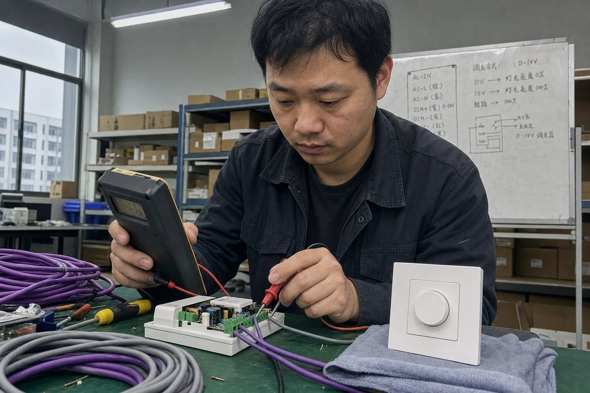
De test is eenvoudig. Plaats een multimeter op de paarse en grijze regeldraden terwijl u de dimmer beweegt. Als u een soepel veranderende gelijkspanning ziet, kijkt u naar een analoog regelsignaal. Een digitaal systeem zoals een DALI-regelsysteem 1 zou een vaste buss panning tonen met datapulsen erop, die een basismeter niet kan decoderen.
Hier is het deel dat mensen in de war brengt. 0–10V is analoog, zelfs wanneer de controller zelf digitaal wordt aangestuurd. A gebouwautomatiseringssysteem 2 kan een digitaal commando ontvangen van een beheerplatform en vervolgens elektronica gebruiken om een 0–10V analoge output te genereren. Het systeem kan digitaal zijn, maar de interface tussen de 0–10V-controller en de LED-driver blijft analoog. Dit is precies het scenario dat mijn Singaporese koper had.
De signaalketen binnen de driver
Er is nog een laag die het waard is om te kennen. Voor een constante-spanning LED-driver, is de praktische signaalketen doorgaans:
0–10V regelsignaal → LED-driver → PWM/stroomregeling → LED-belasting
Moderne drivers fungeren dus vaak als hybride apparaten. Ze bemonsteren de analoge spanning en genereren intern een Pulsbreedtemodulatie 3 output voor soepel, flikker-vrij dimmen. De ingangszijde blijft analoog; de uitgangszijde kan PWM zijn. Dat hybride gedrag maakt de regelmethode niet digitaal. De bepalende vraag is wat er op de regeldraden reist — en hier is dat een gewoon spanningsniveau, geen gecodeerd bericht.
Snelle identificatiechecklist
| Wat u waarneemt | Wat het betekent |
|---|---|
| Soepel variërende gelijkspanning (0–10V) op het regelpaar | Analoog 0–10V dimmen |
| Vaste buss panning met datapulsen (rond 16V) | Digitale DALI-bus |
| Driverdatasheet vermeldt “current sinking, 1–10V” | Analoog, IEC 60929 4-stijl variant |
| Alle armaturen op één paar dimmen samen, geen individuele adressering | Analoog broadcastgedrag |
Op welke kwaliteitsproblemen moet ik letten bij het inkopen van 0–10V dimbare LED-drivers?
Tijdens een batch-QC-review in onze fabriek vorig jaar wezen we een concurrentmonster af dat een klant ons stuurde voor benchmarking. De dimcurve was zo ongelijkmatig dat de output zichtbaar sprong tussen 20% en 30%. Die ene fout zou zijn hotelproject hebben verpest.
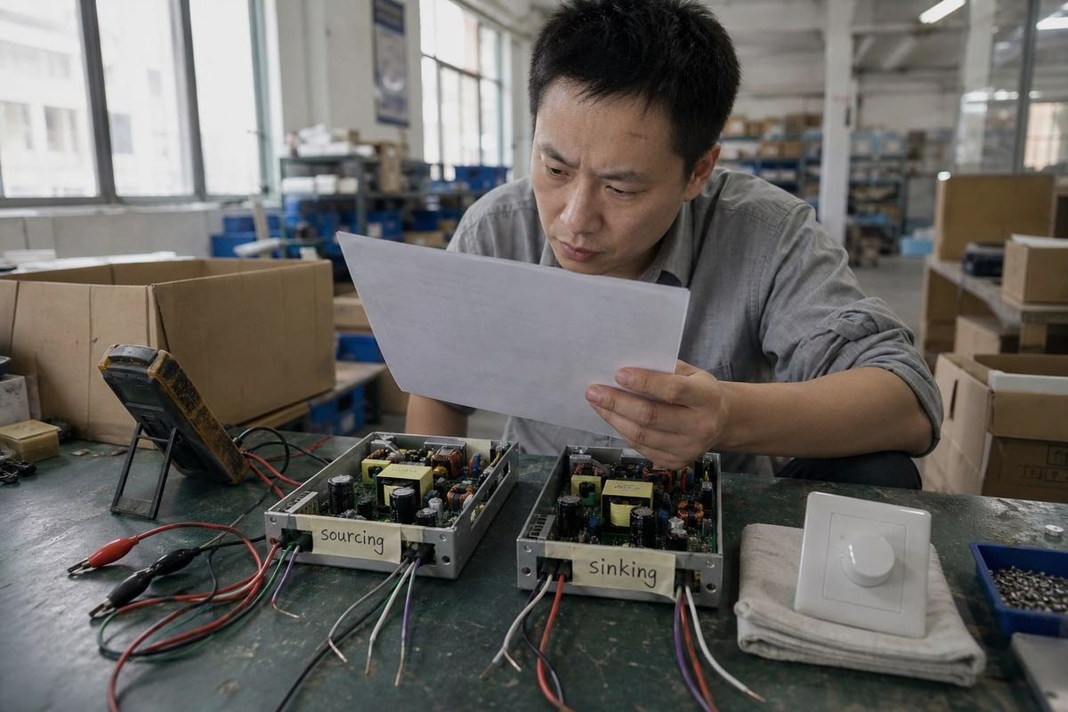
Let op vier problemen: niet-overeenkomende sink- versus source-interfaces, niet-lineaire of inconsistente dimcurves, flikkeren bij lage uitgangsniveaus, en cumulatieve lekstroom op dichtbevolkte circuits die voorkomt dat de spanning laag genoeg daalt om dim-naar-uit te activeren.

Laat me deze uiteenzetten, omdat elk zich anders in het veld manifesteert.
Verschil tussen sinken en sourcen
Dit is de nummer één inkoopval. Er zijn eigenlijk twee veelvoorkomende 0–10V-standaarden, en veel online uitleg vervaagt ze door elkaar:
| Type | Typische functie | Veelvoorkomend gebruik |
|---|---|---|
| 0–10V bron-gestuurd | De regelaar bronnen de stuurspanning; de driver detecteert deze | Theatrale en sommige architectonische systemen |
| 1–10V / IEC 60929-stijl | De driver levert de stuurstroom en de regelaar absorbeert deze; 1V is doorgaans het minimale stuur niveau | Architectonische verlichting, de meeste LED-drivers |
Dus “0–10V” mag niet automatisch als identiek aan “1–10V” worden behandeld. Voordat we een dimmer of driver verzenden, bevestigen we of het systeem van de koper stroomabsorptie of stroombronning verwacht. Het mengen ervan betekent dat de dimmer simpelweg niet werkt, en we hebben distributeurs hele zendingen zien retourneren vanwege dit probleem.
Dimcurve en flikkering
Vraag uw leverancier om de specificatie van de dimcurve — lineair of logaritmisch — en test monsters bij 10%, 5% en 1% output. Goedkope drivers flikkeren vaak hevig onder 10% omdat hun interne pulsbreedtemodulatiefrequentie te laag is. Op onze productielijn testen we elke batch dimbare drivers over het volledige bereik voordat we verpakken, omdat onze technische klanten in Duitsland en Australië het zelf zullen meten.
Lekstroom op dichte circuits
Hier is een subtiel punt. Hoogdichte 0–10V-circuits kunnen last hebben van cumulatieve lekstroom over veel drivers. Die lekstroom kan voorkomen dat de stuurspanning laag genoeg daalt om de dim-naar-uit-status te bereiken. Als uw project veertig drivers op één stuurpaar heeft, controleer dan de lekstroomspecificatie van elke driver en de absorptiecapaciteit van de dimmer. Houd ook rekening met spanningsval over lange stuurleidingen, die het werkelijke dimniveau verschuift van wat de regelaar opdraagt.
Welke certificeringen moet ik verifiëren voor 0–10V-dimcompatibiliteit in mijn projecten?
Nalevingsvragen komen bij bijna elke offerte die we voor Europese en Aziatische klanten voorbereiden. Een verlichtingsdistributeur in Italië heeft ooit een bestelling drie weken vertraagd om slechts één markering dubbel te controleren — een vertraging die goede documentatie had voorkomen.
Verifieer veiligheidscertificeringen die overeenkomen met uw markt (CE, UKCA of regionale equivalenten), EMC-naleving voor signaalintegriteit van de sturing, IEC 60929-conformiteit voor 1–10V-interfaces en Class 2-bedradingsnaleving voor het laagspanningsstuurpaar, inclusief NEC 2020-draadkleurregels voor Noord-Amerikaanse projecten.
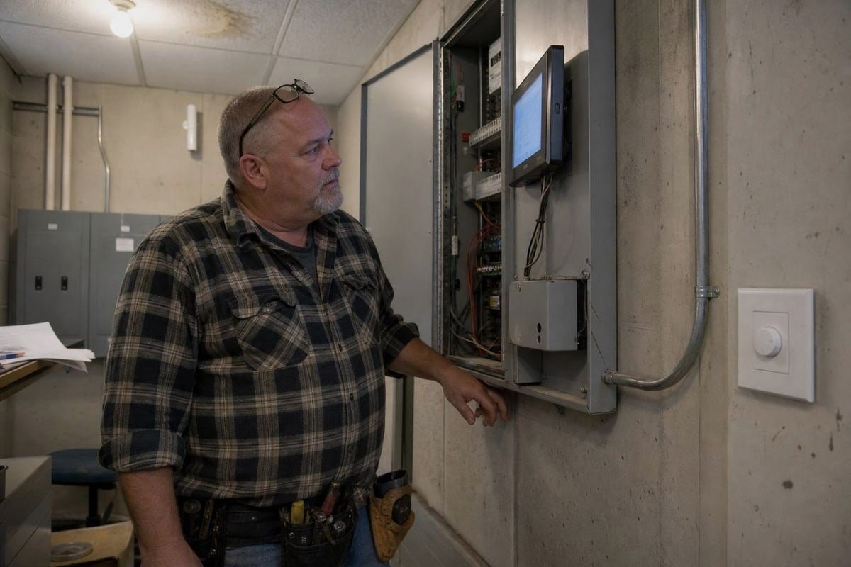
Certificeringen zijn niet alleen papierwerk. Ze vertellen u of de driver en dimmer voorspelbaar gedragen wanneer geïnstalleerd. In onze ervaring met export naar Japan, Italië, Frankrijk, het VK, Duitsland en door heel Zuidoost-Azië, heeft elke markt zijn eigen checklist, en het overslaan van één item stopt douane of faalt bij site-inspectie.
De kernchecklist per categorie
| Categorie | Wat te verifiëren | Waarom het belangrijk is voor 0–10V |
|---|---|---|
| Veiligheid | CE, UKCA of het markteken van het bestemmingsland | Wettelijke markttoegang en basis elektrische veiligheid |
| EMC | Emissie- en immuniteitsnaleving | Voorkomt stuur signaalinterferentie op het 0–10V-paar |
| Interface-standaard | IEC 60929 voor 1–10V-absorberende drivers | Bevestigt dat de diminterface zich gedraagt zoals gedocumenteerd |
| Laagspanningsbedrading | Class 2-bedradingsnaleving | Staat het stuurpaar toe om te werken met eenvoudigere installatieregels |
| Draadidentificatie | NEC 2020-kleurupdates (VS-projecten) | Correcte geleiderkleuren tijdens inspectie |
Het NEC 2020-detail dat de meeste kopers missen
Standaardinstallaties hebben historisch paars gebruikt voor de positieve stuurader en grijs voor de negatieve. Maar NEC 2020 verplicht een verschuiving van grijs naar roze voor de negatieve stuurdraad. De reden is veiligheid: grijs kan worden verward met geaarde neutrale geleiders. Als uw project in Noord-Amerika is, verifieer dan dat de aders of documentatie van uw leverancier deze wijziging weerspiegelen. We hebben onze exportdocumentatie het jaar dat deze regel werd ingevoerd bijgewerkt, en het heeft verschillende klanten gered van inspectievlaggen.
EMC en signaalintegriteit
Een certificeringsgebied dat kopers onderschatten is EMC. Het 0–10V-paar is laagspanning en, over lange leidingen, kwetsbaar voor stuur signaalinterferentie van nabijgelegen stroomgeleiders. Een driver met solide EMC-ontwerp filtert die ruis; een slecht ontworpen driver laat het dimniveau afdwalen of flikkeren. Vraag om EMC-testrapporten, niet alleen het logo op het etiket. Gerenommeerde leveranciers overhandigen deze zonder aarzeling — en bij boqi begeleidt ons technisch supportteam klanten door de rapporten wanneer nodig.

Hoe kies ik tussen analoog 0–10V en digitaal DALI-dimmen voor mijn technische projecten?
Omdat we zowel DALI dimbare drivers als 0–10V dimbare drivers bouwen, heb ik geen belang bij het pushen van de ene boven de andere. Het eerlijke antwoord hangt af van het project — en ik heb meer dan één klant van de duurdere optie afgepraat.
Kies 0–10V voor eenvoudige, kosteneffectieve zone-dimming waarbij alle armaturen op één paar samen dimmen. Kies DALI wanneer je individuele adressering van armaturen, tweerichtingsstatusfeedback, digitale scene-commando's of integratie met een gebouwbeheersysteem nodig hebt.
Hier is het vergelijkende overzicht dat ik voor klanten schets voordat we iets offerten:
| Factor | Analoog 0–10V | Digitaal DALI |
|---|---|---|
| Signaaltype | Continue DC-spanning | Gecodeerde digitale commando's op een bus |
| Adressering | Geen — alle armaturen op het paar dimmen samen | Individuele en groepsadressering |
| Feedback | Unidirectioneel, geen statusbewaking | Tweerichtings; drivers melden fouten en status |
| Scènes | Niet via het dimpaar zelf | Digitale scene-commando's ingebouwd in het protocol |
| Bedrading | Polarisatiegevoelig stuurpaar | Polarisatievrije tweedraadsbus |
| Kosten | Lager per punt | Hoger, maar meer mogelijkheden per punt |
| Inbedrijfstelling | Plug en dim | Vereist adressering en configuratie |
Wanneer 0–10V wint
Magazijnen, hoge hallen, paneelverlichting, parkeergarages — overal waar één zone als blok dimt. Het systeem is eenvoudig, robuust en goedkoop in gebruikname. Aannemers begrijpen het al. En 0–10V evolueert: geavanceerde toepassingen met instelbaar wit gebruiken nu dubbele 0–10V-kanalen, één voor intensiteit en één voor kleurtemperatuur, allemaal via analoge signalen. Analoog betekent niet primitief.
Wanneer DALI wint
Kantoren, ziekenhuizen, hotels en elke locatie die is gekoppeld aan gebouwautomatisering. DALI is digitaal en adresseerbaar, dus je kunt armaturen in software hergroeperen in plaats van opnieuw te bedraden, geplande scènes uitvoeren en foutmeldingen van elke LED-driver ontvangen. Bij een kantoorproject met vijfhonderd armaturen betaalt die flexibiliteit zich meestal terug.
De hybride realiteit
Veel van onze technische klanten combineren beide. Ze gebruiken DALI op kantoorverdiepingen en 0–10V in back-of-house-gebieden. Omdat we beide drivertypen produceren samen met de bijbehorende DALI-controllers en 0–10V-dimmers, leveren we vaak één project met beide — en we zorgen ervoor dat de specificaties voor elke zone worden vastgelegd voordat de productie start. Kort antwoord, zoals ik elke nieuwe klant vertel: 0–10V = analoge aansturing. DALI = digitale aansturing. Kies op basis van hoeveel intelligentie elke ruimte daadwerkelijk nodig heeft.
Conclusie
0–10V-dimming is analoog: een continue spanning bepaalt de helderheid, terwijl DALI digitale commando's verzendt. Controleer sinking versus sourcing, certificeringen en bedradingsregels — en kies dan de aansturingsmethode die je project echt nodig heeft.
Voetnoten
- Officiële industriële alliantie voor DALI, die technische specificaties levert voor digitale lichtsturing. ↩︎
- Bron van het Amerikaanse Ministerie van Energie over bouwsystemen en automatiserings technologieën. ↩︎
- Technische uitleg van de interne uitgangstechniek die LED-drivers gebruiken voor dimmen. ↩︎
- De internationale norm die de 1-10V analoge diminterface voor elektronische voorschakelapparaten definieert. ↩︎