Zum Inhalt wechseln










Ist die 0–10-V-Dimmung analog oder digital? Diese Frage höre ich ständig von Käufern, die unser Sortiment an LED-Treibern prüfen. Wenn man hier einen Fehler macht, leidet die Dimmleistung des gesamten Projekts darunter.
Die 0–10-V-Dimmung ist ein analoges und kein digitales Steuerungsverfahren. Dabei wird eine kontinuierliche Gleichspannung zwischen 0 und 10 Volt verwendet, um den Ausgangspegel des LED-Treibers einzustellen. Im Gegensatz zu DALI, das digitale Befehle über einen Kommunikationsbus überträgt, wird bei 0–10 V die Helligkeit direkt als Spannung dargestellt.
Das ist die kurze Antwort. Doch die Verwirrung rund um dieses Thema ist groß, und sie kostet Ingenieurbüros Geld, wenn die falschen Produkte spezifiziert werden. Lassen Sie mich Ihnen erläutern, worauf es tatsächlich ankommt.
Wie kann ich feststellen, ob mein 0–10-V-Dimm-System analog oder digital ist?
Ein Käufer aus Singapur schrieb mir einmal eine Nachricht auf WhatsApp und war fest davon überzeugt, sein 0–10-V-System sei “digital”, weil sein smarter Regler über eine App verfügte. Ich habe die Verwechslung sofort verstanden – unsere Ingenieure erleben das jede Woche.
Ihr 0–10-V-System ist analog. Der Dimmwert wird als kontinuierliche Gleichspannung über ein spezielles Steuerleitungspaar übertragen, wobei etwa 0 V die minimale Leistung und 10 V die maximale Leistung bedeuten. Auf diesem Leitungspaar gibt es keine codierten Datenpakete, keine Adressierung und keine bidirektionale Rückmeldung.

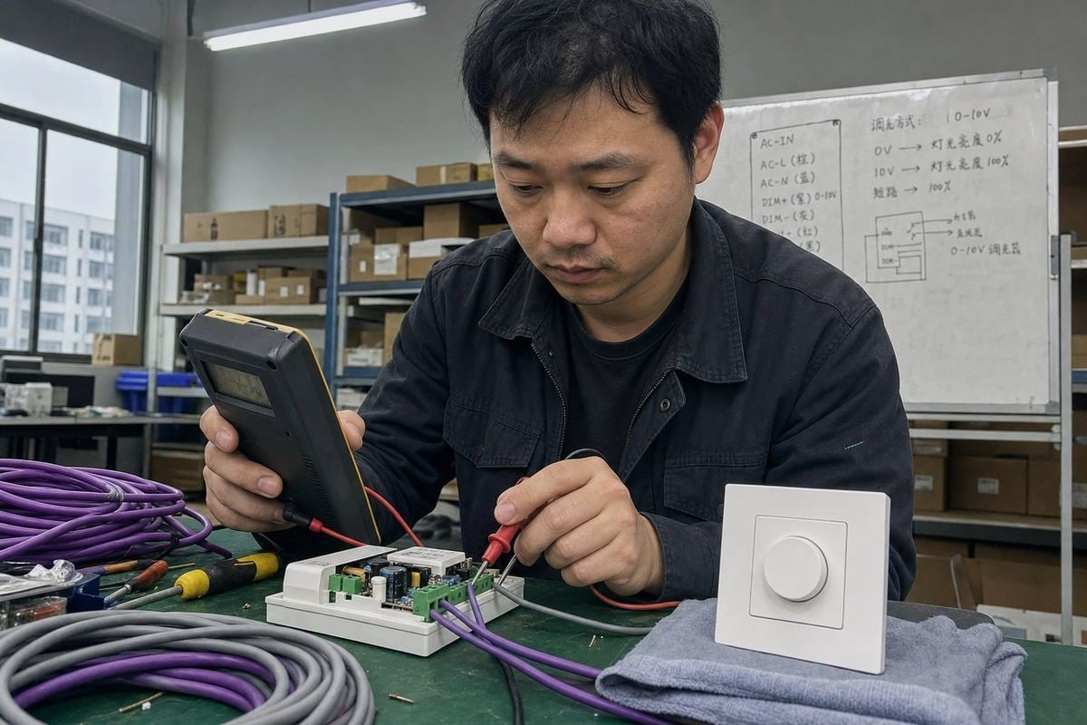
Der Test ist ganz einfach. Schließen Sie ein Multimeter an die violetten und grauen Steuerleitungen an, während Sie den Dimmer betätigen. Wenn Sie eine gleichmäßig ansteigende Gleichspannung messen, handelt es sich um ein analoges Steuersignal. Ein digitales System wie ein DALI-Steuerungssystem 1 würde eine konstante Busspannung anzeigen, auf der Datenimpulse aufliegen, die ein einfaches Messgerät nicht entschlüsseln kann.
Das ist der Punkt, an dem viele ins Straucheln geraten. 0–10 V ist analog, auch wenn der Regler selbst digital gesteuert wird. A Gebäudeautomationssystem 2 kann einen digitalen Befehl von einer Steuerungsplattform empfangen und anschließend mithilfe elektronischer Schaltungen einen analogen 0–10-V-Ausgang erzeugen. Der System mag zwar digital sein, doch die Schnittstelle zwischen dem 0–10-V-Regler und dem LED-Treiber bleibt analog. Genau dieses Szenario hatte mein Käufer aus Singapur.
Die Signalkette im Treiber
Es gibt noch eine weitere Ebene, die man kennen sollte. Für eine LED-Treiber mit konstanter Spannung, die praktische Signalkette sieht in der Regel wie folgt aus:
0–10-V-Steuersignal → LED-Treiber → PWM-/Stromregelung → LED-Last
Daher fungieren moderne Treiber oft als Hybridgeräte. Sie nehmen die analoge Spannung ab und erzeugen intern ein Pulsweitenmodulation 3 Ausgangssignal für eine gleichmäßige, flimmerfreie Dimmung. Die Eingangsseite bleibt analog; die Ausgangsseite kann PWM sein. Dieses hybride Verhalten macht die Steuerungsmethode noch lange nicht zu einer digitalen. Die entscheidende Frage ist, was über die Steuerleitungen übertragen wird – und hier handelt es sich um einen einfachen Spannungspegel, nicht um eine codierte Nachricht.
Checkliste zur schnellen Identifizierung
| Was du beobachtest | Was das bedeutet |
|---|---|
| Stufenlos einstellbare Gleichspannung (0–10 V) am Steuerpaar | Analoges Dimmen 0–10 V |
| Feste Busspannung mit Datenimpulsen (ca. 16 V) | Digitaler DALI-Bus |
| Im Datenblatt des Treibers steht: “Stromsink, 1–10 V” | Analog, IEC 60929 4-Stilvariante |
| Alle Leuchten eines Paares werden gemeinsam gedimmt, keine individuelle Ansteuerung | Verhalten bei analogen Rundfunkübertragungen |
Auf welche Qualitätsaspekte sollte ich bei der Beschaffung von dimmbaren 0–10-V-LED-Treibern achten?
Bei einer stichprobenartigen Qualitätskontrolle in unserem Werk im letzten Jahr haben wir ein Muster eines Mitbewerbers zurückgewiesen, das uns ein Kunde zum Vergleich geschickt hatte. Die Dimmkurve war so ungleichmäßig, dass die Lichtleistung zwischen den Modellen 20% und 30% sichtbar schwankte. Dieser eine Fehler hätte sein Hotelprojekt zunichte gemacht.
Achten Sie auf vier Probleme: nicht aufeinander abgestimmte Sinking- und Sourcing-Schnittstellen, nichtlineare oder inkonsistente Dimmkurven, Flackern bei niedrigen Ausgangspegeln sowie kumulativer Leckstrom in Schaltungen mit hoher Dichte, der verhindert, dass die Spannung so weit abfällt, dass die „Dim-to-Off“-Funktion ausgelöst wird.

Lassen Sie mich das einmal näher erläutern, denn jedes dieser Elemente zeigt sich in der Praxis anders.
Diskrepanz zwischen Verbrauch und Beschaffung
Das ist die größte Falle bei der Beschaffung. Tatsächlich gibt es zwei häufig anzutreffende 0–10-V-Standards, und in vielen Online-Erklärungen werden diese Begriffe miteinander verwechselt:
| Typ | Typische Funktion | Übliche Verwendung |
|---|---|---|
| 0–10 V, quellengesteuert | Der Controller Quellen die Steuerspannung; der Treiber erfasst sie | Theatralische und einige architektonische Systeme |
| 1–10 V / nach IEC 60929 | Der Treiber liefert den Ansteuerstrom und den Regler Spülbecken ; 1 V ist in der Regel der minimale Regelwert | Architekturbeleuchtung, die meisten LED-Treiber |
Daher sollte “0–10 V” nicht automatisch als identisch mit “1–10 V” angesehen werden. Bevor wir einen Dimmer oder Treiber ausliefern, klären wir ab, ob das System des Käufers einen Stromsink- oder einen Stromquellenbetrieb erwartet. Werden diese beiden Modi verwechselt, funktioniert der Dimmer schlichtweg nicht, und wir haben bereits erlebt, dass Händler aus diesem Grund ganze Lieferungen zurückgeschickt haben.
Dimmkurve und Flimmern
Fragen Sie Ihren Lieferanten nach den Angaben zur Dimmkurve – linear oder logarithmisch – und testen Sie Muster bei einer Ausgangsleistung von 10%, 5% und 1%. Billige Treiber oft unter 10% starkes Flackern da ihre interne Pulsweitenmodulationsfrequenz zu niedrig ist. In unserer Fertigungslinie prüfen wir jede Charge dimmbarer Treiber über den gesamten Bereich hinweg, bevor wir sie verpacken, da unsere Kunden aus dem Ingenieurwesen in Deutschland und Australien diese selbst messen werden.
Leckstrom in dicht bestückten Schaltungen
Hier ist ein subtiler Punkt. Bei 0–10-V-Schaltungen mit hoher Dichte kann es zu einem kumulativen Leckstrom über viele Treiber hinweg kommen. Dieser Leckstrom kann verhindern, dass die Steuerspannung so weit abfällt, dass der „Dim-to-Off“-Zustand erreicht wird. Wenn Ihr Projekt vierzig Treiber an einem Steuerpaar umfasst, überprüfen Sie die Leckstromspezifikationen jedes einzelnen Treibers sowie die Stromaufnahmefähigkeit des Dimmers. Berücksichtigen Sie außerdem den Spannungsabfall bei langen Steuerleitungen, der dazu führt, dass der tatsächliche Dimmwert von dem durch den Controller vorgegebenen Wert abweicht.
Welche Zertifizierungen muss ich in meinen Projekten überprüfen, um die Kompatibilität mit der 0–10-V-Dimmung sicherzustellen?
Bei fast jedem Angebot, das wir für europäische und asiatische Kunden erstellen, tauchen Fragen zur Einhaltung von Vorschriften auf. Ein Beleuchtungshändler in Italien hat einmal eine Bestellung um drei Wochen verzögert, nur um eine Kennzeichnung noch einmal zu überprüfen – eine Verzögerung, die durch ordnungsgemäße Dokumentation hätte vermieden werden können.
Überprüfen Sie die für Ihren Markt geltenden Sicherheitszertifizierungen (CE, UKCA oder regionale Äquivalente), die EMV-Konformität hinsichtlich der Integrität der Steuersignale, die Konformität mit der Norm IEC 60929 für 1–10-V-Schnittstellen sowie die Einhaltung der Anforderungen für die Verkabelung der Klasse 2 für das Niederspannungs-Steuerleitungspaar, einschließlich der NEC-2020-Vorschriften zur Aderfarbkennzeichnung für nordamerikanische Projekte.
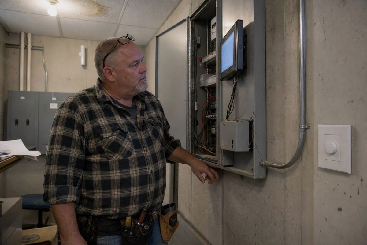
Zertifizierungen sind nicht nur reine Formalitäten. Sie geben Aufschluss darüber, ob sich der Treiber und der Dimmer nach dem Einbau wie erwartet verhalten. Nach unseren Erfahrungen mit dem Export nach Japan, Italien, Frankreich, Großbritannien, Deutschland und in ganz Südostasien hat jeder Markt seine eigene Checkliste, und das Auslassen eines einzelnen Punktes führt zu Verzögerungen beim Zoll oder zum Nichtbestehen der Vor-Ort-Prüfung.
Die Kern-Checkliste nach Kategorien
| Kategorie | Was ist zu überprüfen? | Warum dies für 0–10 V wichtig ist |
|---|---|---|
| Sicherheit | CE-Kennzeichnung, UKCA-Kennzeichnung oder die Kennzeichnung des Bestimmungslandes | Rechtlicher Marktzugang und grundlegende elektrische Sicherheit |
| EMC | Einhaltung von Emissions- und Störfestigkeitsvorschriften | Verhindert Störungen des Steuersignals auf dem 0–10-V-Paar |
| Schnittstellenstandard | IEC 60929 für 1–10-V-Treiber mit Senkbetrieb | Stellt sicher, dass sich die Dimm-Schnittstelle wie dokumentiert verhält |
| Niederspannungsverkabelung | Einhaltung der Anforderungen für die Verkabelung der Klasse 2 | Ermöglicht den Betrieb des Steuerungs-Paares mit einfacheren Installationsvorschriften |
| Leiterkennzeichnung | NEC 2020 – Farbaktualisierungen (Projekte in den USA) | Korrekte Aderfarben bei der Prüfung |
Das Detail der NEC 2020, das die meisten Käufer übersehen
Bei Standardinstallationen wurde bisher für die positive Steuerleitung die Farbe Lila und für die negative die Farbe Grau verwendet. Die NEC 2020 schreibt jedoch vor, dass die Farbe der negativen Steuerleitung von Grau auf Rosa umgestellt werden muss. Der Grund dafür ist die Sicherheit: Grau kann mit geerdeten Neutralleitern verwechselt werden. Wenn Ihr Projekt in Nordamerika durchgeführt wird, vergewissern Sie sich, dass die Anschlussdrähte oder die Dokumentation Ihres Lieferanten diese Änderung widerspiegeln. Wir haben unsere Exportunterlagen bereits in dem Jahr aktualisiert, als diese Vorschrift in Kraft trat, und dadurch konnten wir mehreren Kunden Probleme bei der Abnahme ersparen.
EMV und Signalintegrität
Ein Zertifizierungsbereich, den Einkäufer oft unterschätzen, ist die EMV. Das 0–10-V-Paar ist eine Niederspannungsleitung und bei langen Leitungsstrecken anfällig für Störsignale von nahegelegenen Stromleitungen. Ein Treiber mit solider EMV-Auslegung filtert diese Störungen heraus; ein schlecht konzipierter Treiber lässt den Dimmwert driften oder flackern. Fragen Sie nach EMV-Prüfberichten und verlassen Sie sich nicht nur auf das Logo auf dem Etikett. Seriöse Anbieter händigen diese ohne zu zögern aus – und bei boqi führt unser technischer Support die Kunden bei Bedarf durch die Berichte.

Wie entscheide ich mich bei meinen technischen Projekten zwischen analoger 0–10-V- und digitaler DALI-Dimmung?
Da wir sowohl DALI-dimmbare als auch 0–10-V-dimmbare Treiber herstellen, habe ich kein Interesse daran, eine Variante gegenüber der anderen zu bevorzugen. Die ehrliche Antwort hängt vom jeweiligen Projekt ab – und ich habe schon mehr als einem Kunden von der teureren Variante abgeraten.
Wählen Sie 0–10 V für eine einfache, kostengünstige Zonendimmung, bei der alle Leuchten eines Paares gemeinsam gedimmt werden. Wählen Sie DALI, wenn Sie eine individuelle Adressierung der Leuchten, eine bidirektionale Statusrückmeldung, digitale Szenensteuerbefehle oder die Integration in ein Gebäudeautomationssystem benötigen.

Hier ist die Gegenüberstellung, die ich für Kunden skizziere, bevor wir ein Angebot erstellen:
| Faktor | Analog 0–10 V | Digitales DALI |
|---|---|---|
| Signaltyp | Gleichspannung | Codierte digitale Befehle auf einem Bus |
| Ansprechen | Keine – alle Leuchten des Paares werden gemeinsam gedimmt | Einzel- und Gruppenansprache |
| Feedback | Unidirektional, keine Statusüberwachung | In beide Richtungen: Fahrer melden Störungen und den Status |
| Szenen | Nicht über das Dimmpaar selbst | Im Protokoll integrierte digitale Szenensteuerbefehle |
| Verkabelung | Polaritätsempfindliches Steuerpaar | Polaritätsunabhängiger Zweidrahtbus |
| Kosten | Niedriger pro Punkt | Höher, aber mehr Leistung pro Punkt |
| Inbetriebnahme | Anschließen und dimmen | Muss adressiert und konfiguriert werden |
Wenn 0–10 V die Oberhand gewinnt
Lagerhallen, Hochregallager, Flächenbeleuchtung, Parkhäuser – überall dort, wo ein Bereich als Ganzes gedimmt wird. Das System ist einfach, robust und kostengünstig in der Inbetriebnahme. Die Installateure sind bereits damit vertraut. Und 0–10 V entwickelt sich weiter: Moderne Anwendungen mit einstellbarem Weiß nutzen mittlerweile zwei 0–10-V-Kanäle, einen für die Helligkeit und einen für die Farbtemperatur, alles über analoge Signale. Analog bedeutet nicht gleich primitiv.
Wenn DALI gewinnt
Büros, Krankenhäuser, Hotels und alle Standorte, die an ein Gebäudeautomationssystem angeschlossen sind. DALI ist ein digitales und adressierbares System, sodass Sie Leuchten per Software neu gruppieren können, ohne die Verkabelung ändern zu müssen, zeitgesteuerte Szenarien ausführen und Fehlermeldungen von jedem einzelnen LED-Treiber empfangen können. Bei einem Büroprojekt mit 500 Leuchten macht sich diese Flexibilität in der Regel schon von selbst bezahlt.
Die hybride Realität
Viele unserer Kunden aus dem Ingenieurwesen kombinieren beides. Sie setzen DALI in den Büroetagen und 0–10 V in den hinteren Bereichen ein. Da wir beide Treiberarten sowie die passenden DALI-Steuerungen und 0–10-V-Dimmer herstellen, beliefern wir ein Projekt oft mit beidem – und stellen sicher, dass die Spezifikationen für jede Zone vor Produktionsbeginn feststehen. Die kurze Antwort, die ich jedem neuen Kunden gebe, lautet: 0–10 V = analoge Steuerung. DALI = digitale Steuerung. Entscheide dich danach, wie viel Intelligenz jeder Bereich tatsächlich benötigt.
Abschluss
Die 0–10-V-Dimmung erfolgt analog: Die Helligkeit wird durch eine stufenlose Spannung geregelt, während DALI digitale Befehle sendet. Prüfen Sie, ob es sich um „Sinking“ oder „Sourcing“ handelt, sowie die Zertifizierungen und Verkabelungsvorschriften – und wählen Sie dann die Steuerungsmethode, die Ihr Projekt tatsächlich benötigt.
Fußnoten
- Offizieller Branchenverband für DALI, der technische Spezifikationen für die digitale Beleuchtungssteuerung bereitstellt. ↩︎
- Informationsquelle des US-Energieministeriums zu Gebäudesystemen und Automatisierungstechnologien. ↩︎
- Technische Erläuterung der internen Ausgangstechnik, die von LED-Treibern zum Dimmen verwendet wird. ↩︎
- Die internationale Norm, die die analoge 1–10-V-Dimm-Schnittstelle für elektronische Vorschaltgeräte definiert. ↩︎