Skip to content









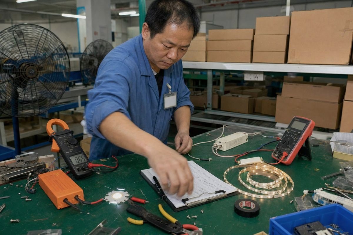
การเลือกระหว่างไดรเวอร์ LED 0–10V แบบกระแสคงที่และแรงดันคงที่ทำให้แม้แต่ผู้ซื้อที่มีประสบการณ์ยังสับสน ฉันเคยเห็นการเลือกที่ผิดในสายการผลิตของเราทำให้เกิดการกะพริบ ความร้อนสูงเกินไป และความเสียหายของ LED ก่อนเวลาอันควร ไดรเวอร์ที่จับคู่ผิดเพียงตัวเดียวสามารถทำลายชุดโคมไฟทั้งหมดได้—และค่าใช้จ่ายในการส่งคืนเพียงอย่างเดียวก็สามารถทำกำไรของโครงการคุณหายไป ข่าวดี? การตัดสินใจจะง่ายขึ้นเมื่อคุณแยกสัญญาณการหรี่แสงออกจากประเภทการควบคุมเอาต์พุต.
เลือกไดรเวอร์ LED 0–10V แบบกระแสคงที่เมื่อ LED ของคุณระบุกระแสขับ เช่น 350mA, 700mA หรือ 1A เลือกไดรเวอร์ 0–10V แบบแรงดันคงที่เมื่อผลิตภัณฑ์ LED ของคุณต้องการแหล่งจ่าย DC คงที่ 12V หรือ 24V เช่น แถบ LED ที่มีตัวจำกัดกระแสในตัว.
นั่นคือคำตอบสั้นๆ แต่ยังมีรายละเอียดเพิ่มเติม สัญญาณ 0–10V บอกให้ไดรเวอร์หรี่แสงได้มากแค่ไหนเท่านั้น ไม่ได้ตัดสินใจว่าไดรเวอร์เป็นแบบ CC หรือ CV ให้ฉันอธิบายรายละเอียดเพื่อให้คุณไม่ซื้อหน่วยที่ผิดอีกต่อไป.
ความแตกต่างหลักระหว่างไดรเวอร์ LED 0–10V แบบกระแสคงที่และแรงดันคงที่คืออะไร?
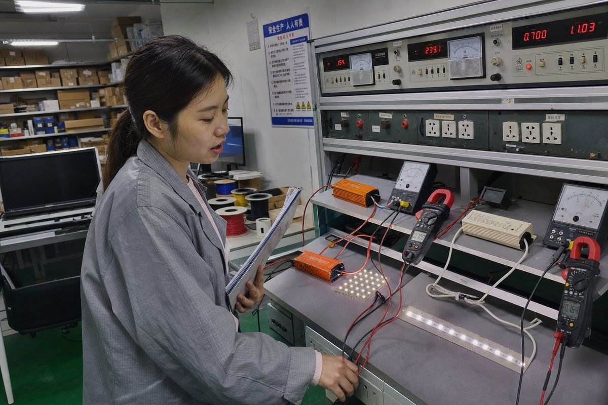
เมื่อเราปรับเทียบไดรเวอร์ 0–10V ที่โรงงานของเรา สิ่งแรกที่แท่นทดสอบของเราตรวจสอบคือโหมดเอาต์พุต หน่วย CC และหน่วย CV มีพฤติกรรมแตกต่างกันอย่างสิ้นเชิงภายใต้โหลด แม้ว่าทั้งคู่จะรับสัญญาณการหรี่แสงแบบแอนะล็อกเดียวกันก็ตาม.
ไดรเวอร์ 0–10V แบบกระแสคงที่รักษากระแสเอาต์พุตให้คงที่ในขณะที่แรงดันไฟฟ้าแปรผันภายในช่วงแรงดันไปข้างหน้า ไดรเวอร์ 0–10V แบบแรงดันคงที่รักษาแรงดันเอาต์พุตให้คงที่ โดยทั่วไปคือ 12V หรือ 24V DC ในขณะที่กระแสแปรผันตามโหลด อินพุต 0–10V ควบคุมเฉพาะระดับการหรี่แสงเท่านั้น.
นี่คือการเปรียบเทียบหลักโดยสรุป:
| คุณสมบัติ | กระแสคงที่ (CC) | แรงดันคงที่ (CV) |
|---|---|---|
| เอาต์พุตที่ควบคุม | กระแส (เช่น 350mA, 700mA, 1A) | แรงดัน (เช่น 12V, 24V DC) |
| ฉลากระบุ | กระแสคงที่ + ช่วงแรงดัน | แรงดันคงที่ + กระแสสูงสุด |
| การเดินสายทั่วไป | อนุกรม | ขนาน |
| โหลดที่เหมาะสมที่สุด | โมดูล LED แบบ COB, โคมไฟกำลังสูง | แถบ LED, โมดูลป้าย |
| การจำกัดกระแส | จัดการโดยไดรเวอร์ | ต้องสร้างไว้ในผลิตภัณฑ์ LED |
| วิธีการหรี่แสง | การลดกระแสคงที่ (CCR) | มักใช้ การมอดูเลตความกว้างพัลส์ 1 (PWM) |
CC ควบคุมกระแส, CV รักษาแรงดัน
ความแตกต่างจำง่าย: CC ควบคุมกระแส LED; CV รักษาแรงดัน LED ไดรเวอร์ CC ปรับแรงดันเอาต์พุตขึ้นหรือลงภายในช่วงที่ยอมรับได้เพื่อให้กระแสคงที่ตามค่าที่กำหนด ซึ่งปกป้องชิป LED จากการเกินกระแสและ การหนีความร้อน 2. ไดรเวอร์ CV ทำตรงกันข้าม มันล็อกแรงดันที่ 12V หรือ 24V และปล่อยให้โหลดที่เชื่อมต่อดึงกระแสตามที่ต้องการ สูงสุดตามขีดจำกัด.
สัญญาณ 0–10V เข้ามาอยู่ตรงไหน
มุมนี้ อินเทอร์เฟซ 0–10V เป็นสัญญาณการหรี่แสงแบบแอนะล็อก ไม่ใช่ประเภทเอาต์พุตกำลัง เป็นมาตรฐานควบคุมแรงดันต่ำ: 10V สั่งความสว่างเต็มที่, 0V สั่งเอาต์พุตต่ำสุดหรือปิด ขึ้นอยู่กับว่าไดรเวอร์มีความสามารถหรี่ถึงปิดหรือไม่ ไดรเวอร์ทั้งแบบ CC และ CV สามารถรับสัญญาณนี้ได้ ไดรเวอร์ทำหน้าที่เป็นตัวแปล ในระบบ CC ไดรเวอร์ลดกระแสตามสัญญาณ ในระบบ CV ไดรเวอร์โดยทั่วไปปรับเอาต์พุตโดยใช้ PWM เมื่อเราออกแบบวงจรการหรี่แสง เรายังตรวจสอบพฤติกรรมกระแสแบบซิงก์และซอร์สที่ฝั่งควบคุมด้วย เพราะความไม่ตรงกันที่นั่นทำให้สายการหรี่แสงตายแม้ว่าการเดินสายไฟจะสมบูรณ์แบบ.
ฉันจะกำหนดได้อย่างไรว่าไดรเวอร์ LED ประเภทใดเหมาะกับข้อกำหนดการผลิตของฉัน?
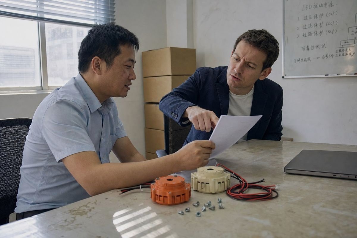
ผู้ซื้อจากฝรั่งเศสเคยส่งสเปกโคมไฟให้เราโดยระบุเพียงกำลังไฟ—ไม่มีกระแส ไม่มีแรงดัน เราต้องส่งกลับพร้อมคำถามเดียว: ดาต้าชีต LED ระบุว่าอะไร? เอกสารฉบับเดียวนั้นตัดสินใจทุกอย่าง.
อ่าน datasheet ของ LED ก่อน หากระบุกระแสขับเคลื่อนเป็น mA หรือ A ให้เลือกไดรเวอร์กระแสคงที่ที่ตรงกับค่าที่ระบุนั้น หากระบุแรงดันไฟฟ้าทำงานเป็น VDC เช่น 12V หรือ 24V ให้เลือกไดรเวอร์แรงดันคงที่ที่มีกำลังไฟฟ้าสำรองเพียงพอ.
ทำตามกระบวนการตัดสินใจง่ายๆ นี้ก่อนทุกคำสั่งซื้อ:
- ตรวจสอบดาต้าชีต LED. กระแสในหน่วย mA หมายถึง CC แรงดันในหน่วย VDC หมายถึง CV กำลังไฟเพียงอย่างเดียวไม่เพียงพอที่จะตัดสินใจ.
- ตรวจสอบโครงสร้างการเดินสาย. การเดินสายแบบอนุกรมเทียบกับแบบขนานมีความสำคัญ โซ่ชิปแบบอนุกรมหรือโมดูล LED แบบ COB ต้องใช้ CC โมดูลและแถบที่เชื่อมต่อแบบขนานต้องใช้ CV.
- ตรวจสอบช่วงแรงดันไปข้างหน้า. สำหรับไดรเวอร์แบบ CC แรงดันไปข้างหน้าทั้งหมดของสาย LED ของคุณต้องอยู่ในช่วงหน้าต่างแรงดันเอาต์พุตของไดรเวอร์.
- ตรวจสอบอินเทอร์เฟซการหรี่แสง. ยืนยันว่าไดรเวอร์เป็นรุ่น CC ที่หรี่แสงได้ 0–10V หรือรุ่น CV ที่หรี่แสงได้ 0–10V โดยเฉพาะ โปรโตคอลการหรี่แสงไม่เคยกำหนดประเภทเอาต์พุต.
- ตรวจสอบข้อกำหนดระดับความปลอดภัย. สำหรับการติดตั้งแรงดันต่ำหลายๆ แบบ แหล่งจ่ายไฟ Class 2 3 ช่วยให้การปฏิบัติตามข้อกำหนดการเดินสายและการตรวจสอบง่ายขึ้น.
เหตุใดการเดินสายแบบอนุกรมเทียบกับแบบขนานจึงสำคัญ
ระบบ CC โดยทั่วไปเป็นแบบอนุกรม LED ทุกดวงในสายโซ่ได้รับกระแสเท่ากัน ดังนั้นความสว่างจึงสม่ำเสมอทั่วทั้งสาย ระบบ CV โดยทั่วไปเป็นแบบขนาน แต่ละโมดูลหรือส่วนของแถบเชื่อมต่อกับรางแรงดันเดียวกัน ซึ่งทำให้ง่ายต่อการเพิ่มหรือถอดโคมไฟระหว่างการเปลี่ยนแปลงเค้าโครง จากประสบการณ์ของเราในการส่งออกไดรเวอร์ไปยังลูกค้าในยุโรป การผสมโทโพโลยีเหล่านี้เป็นสาเหตุอันดับหนึ่งของความล้มเหลวในภาคสนาม โหลดแบบขนานบนไดรเวอร์ CC บังคับให้การแบ่งกระแสไม่เท่ากัน สายอนุกรมยาวบนไดรเวอร์ CV จะไม่สว่างอย่างถูกต้อง.
การจับคู่นอกเหนือจากวัตต์
สำหรับการเลือก CC ให้จับคู่พิกัดมิลลิแอมป์อย่างแม่นยำ — 350mA, 700mA หรือ 1A เป็นค่าที่เราจัดส่งบ่อยที่สุด สำหรับการเลือก CV ตรวจสอบให้แน่ใจว่าความจุวัตต์ทั้งหมดของไดรเวอร์เกินผลรวมของโหลดที่เชื่อมต่อทั้งหมด โดยควรมีพื้นที่เผื่อ 20% การสลับไดรเวอร์ CC และ CV เพียงเพราะวัตต์ตรงกันเป็นความผิดพลาดที่เราเห็นซ้ำแล้วซ้ำเล่า และมักจะจบลงด้วย โคมไฟที่เสียหายหรือกะพริบ.
ปัจจัยด้านต้นทุนใดที่ฉันควรพิจารณาเมื่อเลือกไดรเวอร์ LED แบบ 0–10V สำหรับการผลิตในระดับขนาดใหญ่?
มีการแลกเปลี่ยนที่ฉันชั่งน้ำหนักกับทุกใบเสนอราคาปริมาณมากที่เราเตรียม: ราคาต่อหน่วยเทียบกับต้นทุนระบบทั้งหมด ไดรเวอร์ที่ถูกที่สุดในใบแจ้งหนี้ไม่ค่อยเป็นไดรเวอร์ที่ถูกที่สุดในผลิตภัณฑ์สำเร็จรูป.
สำหรับการผลิตในระดับขนาดใหญ่ ให้ประเมินต้นทุนรวมของระบบ ไม่ใช่ราคาต่อหน่วยของไดรเวอร์ ไดรเวอร์แบบ CV มีต้นทุนต่อหน่วยต่ำกว่าและทำให้การจัดวางแบบขนานง่ายขึ้น แต่ไดรเวอร์แบบ CC ช่วยลดอัตราความล้มเหลว การเรียกร้องค่าสินไหมทดแทนตามการรับประกัน และการสูญเสียในสายไฟ พิจารณาถึงการเดินสายไฟ ระยะห่างเหนือศีรษะ คุณภาพการหรี่แสง และข้อกำหนดการรับรองด้วย.
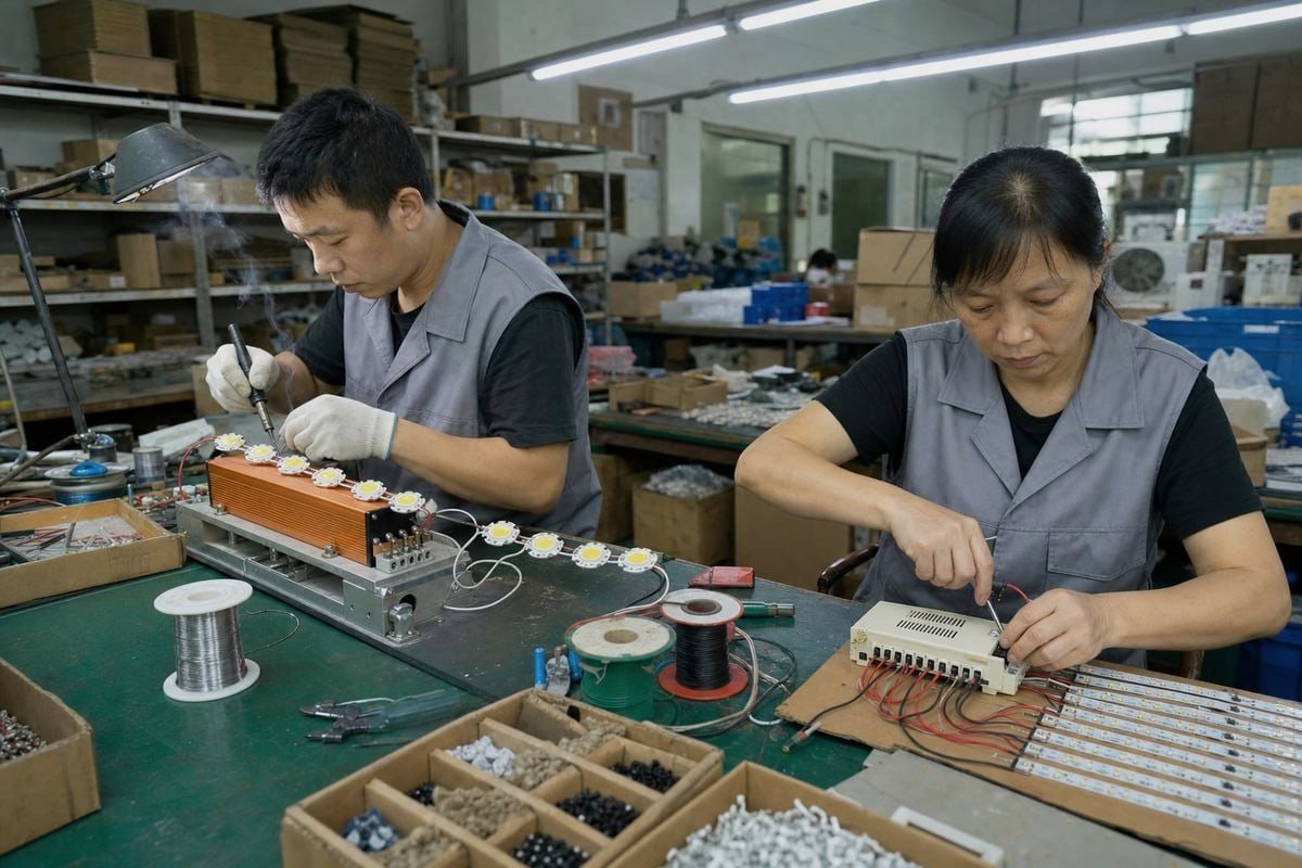
นี่คือวิธีที่ปัจจัยด้านต้นทุนมักจะแยกย่อยเมื่อเราช่วยลูกค้างบประมาณโครงการ:
| ปัจจัยต้นทุน | ผลกระทบของกระแสคงที่ | ผลกระทบของแรงดันคงที่ |
|---|---|---|
| ราคาต่อหน่วยไดรเวอร์ | สูงกว่าต่อหน่วย | ต่ำกว่าต่อหน่วย |
| การเดินสายและสายเคเบิล | ทนทานต่อแรงดันตกในระยะทางยาว | แรงดันตกบังคับให้ใช้สายที่หนาขึ้นหรือระยะทางสั้นลง |
| ความสามารถในการขยาย | หนึ่งไดรเวอร์ต่อโคมไฟหรือสาย | ไดรเวอร์ขนาดใหญ่หนึ่งตัวสามารถป้อนโมดูลขนานหลายตัว |
| ความเสี่ยงด้านความล้มเหลวและการรับประกัน | ต่ำกว่า; กระแสถูกควบคุม | สูงกว่าหากการจำกัดกระแสฝั่ง LED อ่อนแอ |
| ต้นทุนคุณภาพการหรี่แสง | CCR เรียบเนียน ไม่ต้องใช้อะไหล่เพิ่ม | PWM อาจต้องมีการลดการกะพริบสำหรับงานระดับพรีเมียม |
ต้นทุนที่ซ่อนเร้นของแรงดันตก
ไดรเวอร์ CC เพิ่มแรงดันเอาต์พุตโดยอัตโนมัติเพื่อเอาชนะความต้านทานของสายเคเบิล ทำให้ทนทานต่อแรงดันตกในระยะทางยาวโดยธรรมชาติ ระบบ CV ไม่มีความหรูหรานั้น ในการติดตั้งแถบ 12V สายป้อนยาวสามารถทำให้ปลายไกลของรันมืดลงอย่างเห็นได้ชัด การแก้ไขหมายถึงทองแดงที่หนาขึ้น ส่วนที่สั้นลง หรือจุดป้อนเพิ่มเติม — ทั้งหมดเป็นเงินจริงในระดับการผลิต เมื่อเราเสนอราคาโครงการป้ายขนาดใหญ่ ขนาดสายเคเบิลมักเป็นรายการที่ทำให้ผู้ซื้อประหลาดใจที่สุด.
ความเป็นโมดูลาร์เทียบกับการป้องกัน
ลูกค้าบางรายโต้แย้งว่า CC เป็นการลงทุนที่ดีกว่าเสมอเพราะปกป้อง LED และปรับปรุงประสิทธิภาพ คนอื่นยืนยันว่า CV ชนะเพราะถูกกว่าและปรับโครงสร้างใหม่ได้ง่ายกว่า ทั้งสองมุมมองถูกครึ่งหนึ่ง CC เหมาะทางเทคนิคสำหรับตัวเปล่งแสงเปลือยและโคมไฟกำลังสูง CV ประหยัดกว่าอย่างแท้จริงสำหรับผลิตภัณฑ์แรงดันต่ำที่ออกแบบไว้ล่วงหน้าซึ่งการจำกัดกระแสอยู่ในโมดูลแล้ว ลูกค้าบางรายของเรายังระบุไดรเวอร์ไฮบริด CV+CC ซึ่งทำงานในโหมดแรงดันคงที่ภายใต้โหลดปกติแต่สลับเป็นโหมดกระแสคงที่ระหว่างเหตุการณ์กระแสเกิน การป้องกันแบบไฮบริดนั้นมีต้นทุนเพิ่มขึ้นเล็กน้อยล่วงหน้าแต่ป้องกันความล้มเหลวของระบบที่ร้ายแรง — ข้อโต้แย้งที่แข็งแกร่งในการติดตั้งเชิงพาณิชย์ที่ไม่มีคนดูแล.
แอปพลิเคชันใดทำงานได้ดีที่สุดกับระบบหรี่แสง 0–10V แบบกระแสคงที่เทียบกับแรงดันคงที่?
ในช่วงต้นอาชีพของฉันที่โรงงานไฟ LED ฉันเห็นคำสั่งซื้อไฟสตูดิโอถูกปฏิเสธเพราะแถบไฟกะพริบในกล้อง โคมไฟดูสมบูรณ์แบบต่อตา เซนเซอร์กล้องไม่เห็นด้วย.
ไดรเวอร์ 0–10V กระแสคงที่ทำงานได้ดีที่สุดสำหรับดาวน์ไลท์ ไฟแผง โคมไฟไฮเบย์ และโคมไฟที่ใช้ COB ที่ต้องการความสว่างสม่ำเสมอ ระบบ 0–10V แรงดันคงที่เหมาะกับแถบ LED ป้าย ไฟโคฟ และแอปพลิเคชันเน้นเสียงที่สร้างจากโมดูลแบบขนาน.
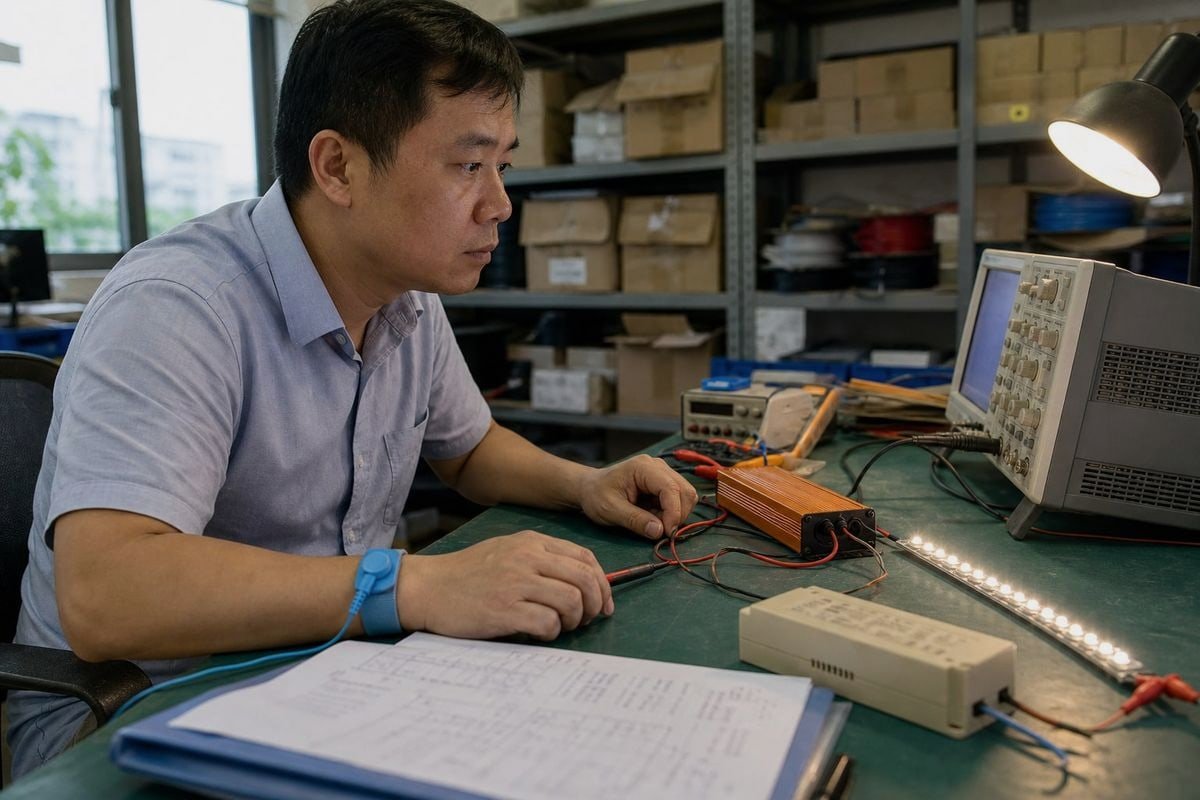
จับคู่แอปพลิเคชันกับประเภทไดรเวอร์โดยใช้ข้อมูลอ้างอิงนี้:
| การใช้งาน | ประเภทที่แนะนำ | เหตุผล |
|---|---|---|
| ดาวน์ไลท์ฝังเพดานและสปอตไลท์ | CC | ชิปแบบอนุกรมต้องการกระแสที่แม่นยำสำหรับเอาต์พุตที่สม่ำเสมอ |
| ไฮเบย์และโคมไฟอุตสาหกรรม | CC | ตัวเปล่งแสงกำลังสูงต้องการการป้องกันกระแสเกิน |
| ฟิล์มและการจัดแสงสำหรับการออกอากาศ | CC พร้อม CCR ความถี่สูง | ขจัดแถบแสงที่จับได้โดยเซนเซอร์กล้องความเร็วสูง |
| ไฟแถบ LED และเทปไฟ | ประวัติย่อ | แถบมีตัวต้านทานในตัวและต้องการไฟ 12V/24V ที่เสถียร |
| ป้ายไฟและตัวอักษรเรืองแสง | ประวัติย่อ | โมดูลแบบขนานง่ายต่อการเพิ่ม ถอด และเปลี่ยน |
| ไฟร่องและไฟเน้นแสง | ประวัติย่อ | ความยาวที่ยืดหยุ่นและการปรับเปลี่ยนภาคสนามที่ง่าย |
พฤติกรรมการหรี่แสงในโคมไฟจริง
คุณภาพการหรี่แสงคือจุดที่การใช้งานแตกต่างกันอย่างแท้จริง ไดรเวอร์ CC มักจะหรี่แสงผ่านการลดกระแสคงที่ (Constant Current Reduction) ซึ่งลดกระแสแบบอะนาล็อกอย่างราบรื่น เหมาะสำหรับการส่องสว่างทั่วไป และระบบ 0–10V ที่ออกแบบมาอย่างดีสามารถหรี่แสงได้อย่างราบรื่นลงถึง 10%, 1% และแม้แต่ 0.1% ในบางการกำหนดค่า ระบบ CV มักจะพึ่งพาการมอดูเลตความกว้างพัลส์ (PWM) ซึ่งหมุนเวียนเอาต์พุตอย่างรวดเร็ว PWM นั้นใช้ได้ดีสำหรับงานตกแต่งส่วนใหญ่ แต่ PWM ความถี่ต่ำสามารถทำให้เกิด การกะพริบที่มองเห็นได้ 4 หรือแถบแสงจากกล้อง สำหรับสภาพแวดล้อมวิดีโอ CCR ความถี่สูงบนไดรเวอร์ CC เป็นข้อกำหนดที่ปลอดภัยกว่า.
เส้นโค้งการหรี่แสงและการรับรู้ของมนุษย์
อีกรายละเอียดหนึ่งที่วิศวกรของเราเน้นสำหรับโปรเจกต์ระดับพรีเมียม: รูปร่างของเส้นโค้งการหรี่แสง คอนโทรลเลอร์ 0–10V ส่วนใหญ่ส่งสัญญาณแบบเส้นตรง แต่ดวงตามนุษย์รับรู้แสงแบบไม่เป็นเส้นตรง ไดรเวอร์ CC ระดับสูงสามารถตั้งโปรแกรมด้วยเส้นโค้งการหรี่แสงแบบลอการิทึม เพื่อให้การหรี่แสงที่รับรู้ได้รู้สึกเป็นธรรมชาติตลอดช่วงทั้งหมด หากโปรเจกต์ของคุณต้องการความสามารถในการหรี่จนปิดสนิท โปรดยืนยันว่าไดรเวอร์รองรับอย่างชัดเจน — ไดรเวอร์ 0–10V มาตรฐานหลายตัวหรี่ได้เพียงถึงระดับต่ำสุดเท่านั้นและไม่ปิดสนิทหากไม่มีรีเลย์แยกต่างหาก.

บทสรุป
จับคู่โหลดก่อน แล้วจึงจับคู่วิธีการหรี่แสง หาก LED ของคุณระบุกระแส ให้เลือก CC หากระบุแรงดัน ให้เลือก CV ถือว่า 0–10V เป็นเพียงอินเทอร์เฟซการหรี่แสงเท่านั้น — และตรวจสอบความเข้ากันได้ก่อนสั่งซื้อในปริมาณมาก.
เชิงอรรถ
- อธิบายวิธีการหรี่แสงทางเทคนิคที่ไดรเวอร์ CV ใช้ทั่วไปในการควบคุมความสว่าง. ↩︎
- ข้อมูลพื้นฐานเกี่ยวกับโหมดความล้มเหลวจากความร้อนสูงเกินไปที่การควบคุมกระแสคงที่ป้องกันใน LED. ↩︎
- IEEE ครอบคลุมการจำแนกความปลอดภัยทางไฟฟ้าที่เกี่ยวข้องกับการออกแบบแหล่งจ่ายไฟแรงดันต่ำ. ↩︎
- ENERGY STAR ให้คำแนะนำที่เชื่อถือได้เกี่ยวกับมาตรฐานประสิทธิภาพการกะพริบในผลิตภัณฑ์ไฟ LED. ↩︎