Lewati ke konten











Memilih antara driver LED arus konstan dan tegangan konstan 0–10V bisa membingungkan bahkan bagi pembeli yang berpengalaman sekalipun. Saya pernah menyaksikan pemilihan driver yang salah di lini produksi kami menyebabkan kedipan, panas berlebih, dan kegagalan LED dini. Satu driver yang tidak sesuai saja dapat merusak seluruh batch lampu — dan biaya pengiriman pengembalian saja sudah cukup untuk menghabiskan margin proyek Anda. Kabar baiknya? Keputusan ini menjadi sederhana begitu Anda memisahkan sinyal peredupan dari jenis regulasi keluaran.
Pilihlah driver LED arus konstan 0–10V jika LED Anda mensyaratkan arus penggerak tertentu, seperti 350mA, 700mA, atau 1A. Pilih driver tegangan konstan 0–10V jika produk LED Anda memerlukan catu daya DC tetap 12V atau 24V, seperti strip LED dengan pembatas arus terintegrasi.
Itulah jawaban singkatnya. Namun, ada hal lain yang perlu diperhatikan. Sinyal 0–10V hanya memberi tahu pengendali seberapa besar tingkat peredupan yang harus diterapkan. Sinyal tersebut tidak menentukan apakah pengendali tersebut berjenis CC atau CV. Izinkan saya menjelaskan detailnya agar Anda tidak pernah lagi membeli unit yang salah.
Apa Saja Perbedaan Utama Antara Driver LED Arus Konstan dan Tegangan Konstan 0–10 V?
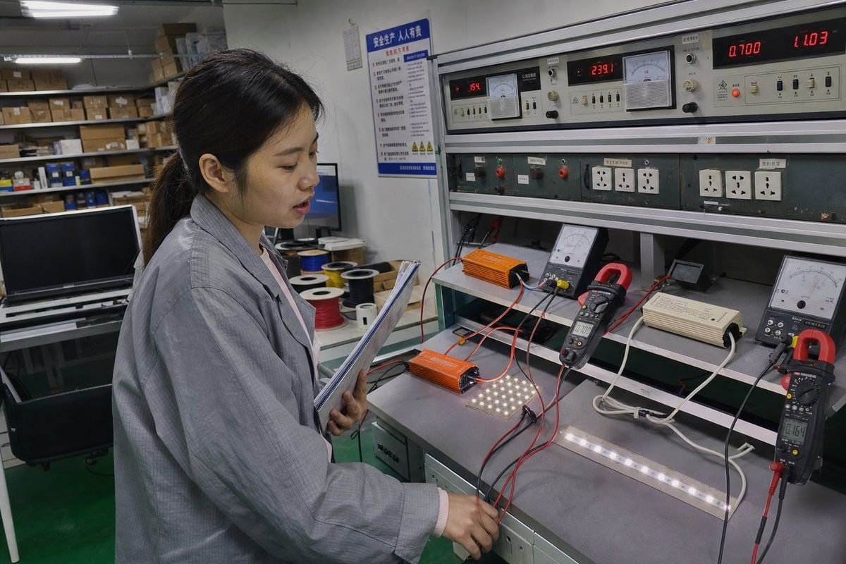
Saat kami mengkalibrasi driver 0–10V di pabrik kami, hal pertama yang diperiksa oleh alat uji kami adalah mode keluaran. Unit CC dan unit CV berperilaku sangat berbeda saat diberi beban, meskipun keduanya menerima sinyal peredupan analog yang sama.
Penggerak arus konstan 0–10 V menjaga arus keluaran tetap konstan sementara tegangan bervariasi dalam rentang tegangan maju. Penggerak tegangan konstan 0–10 V menjaga tegangan keluaran tetap konstan, biasanya 12 V atau 24 V DC, sementara arus bervariasi sesuai dengan beban. Masukan 0–10 V hanya mengontrol tingkat peredupan.
Berikut ini adalah perbandingan inti secara sekilas:
| Fitur | Arus Konstan (CC) | Tegangan Konstan (CV) |
|---|---|---|
| Output yang diatur | Arus (misalnya, 350 mA, 700 mA, 1 A) | Tegangan (misalnya, 12 V, 24 V DC) |
| Tertulis di label | Rentang arus tetap + tegangan | Tegangan tetap + arus maksimum |
| Pemasangan kabel yang umum | Seri | Paralel |
| Beban yang paling sesuai | Modul LED COB, perlengkapan penerangan berdaya tinggi | Lampu strip LED, modul papan tanda |
| Pembatasan arus | Ditangani oleh pengemudi | Harus terintegrasi ke dalam produk LED |
| Metode peredupan | Pengurangan Arus Konstan (CCR) | Seringkali modulasi lebar pulsa 1 (PWM) |
CC Mengatur Arus, CV Menjaga Tegangan
Perbedaannya mudah diingat: CC mengatur arus LED; CV menjaga tegangan LED. Driver CC menyesuaikan tegangan keluarannya naik atau turun dalam rentang kepatuhan sehingga arus tetap tepat pada nilai pengenal. Hal ini melindungi chip LED dari arus berlebih dan lompatan suhu 2. Pengatur tegangan CV justru bekerja sebaliknya. Pengatur ini mengunci tegangan pada 12 V atau 24 V dan memungkinkan beban yang terhubung menarik arus sebanyak yang dibutuhkannya, hingga batas maksimum.
Di Mana Sinyal 0–10 V Digunakan
The Antarmuka 0–10 V adalah sinyal peredupan analog, bukan tipe keluaran daya. Ini merupakan standar kontrol tegangan rendah: 10V menginstruksikan kecerahan penuh, sedangkan 0V menginstruksikan keluaran minimum atau mati, tergantung apakah driver tersebut mendukung fitur “dim-to-off”. Baik driver CC maupun CV dapat menerima sinyal ini. Driver bertindak sebagai penerjemah. Dalam sistem CC, driver mengurangi arus sebagai respons terhadap sinyal. Dalam sistem CV, driver biasanya memodulasi output menggunakan PWM. Saat merancang sirkuit peredupan, kami juga memverifikasi perilaku arus sink versus arus source di sisi kontrol, karena ketidaksesuaian di sana dapat menyebabkan jalur peredupan mati meskipun kabel daya sudah sempurna.
Bagaimana Cara Menentukan Jenis Driver LED yang Sesuai dengan Kebutuhan Produksi Saya?
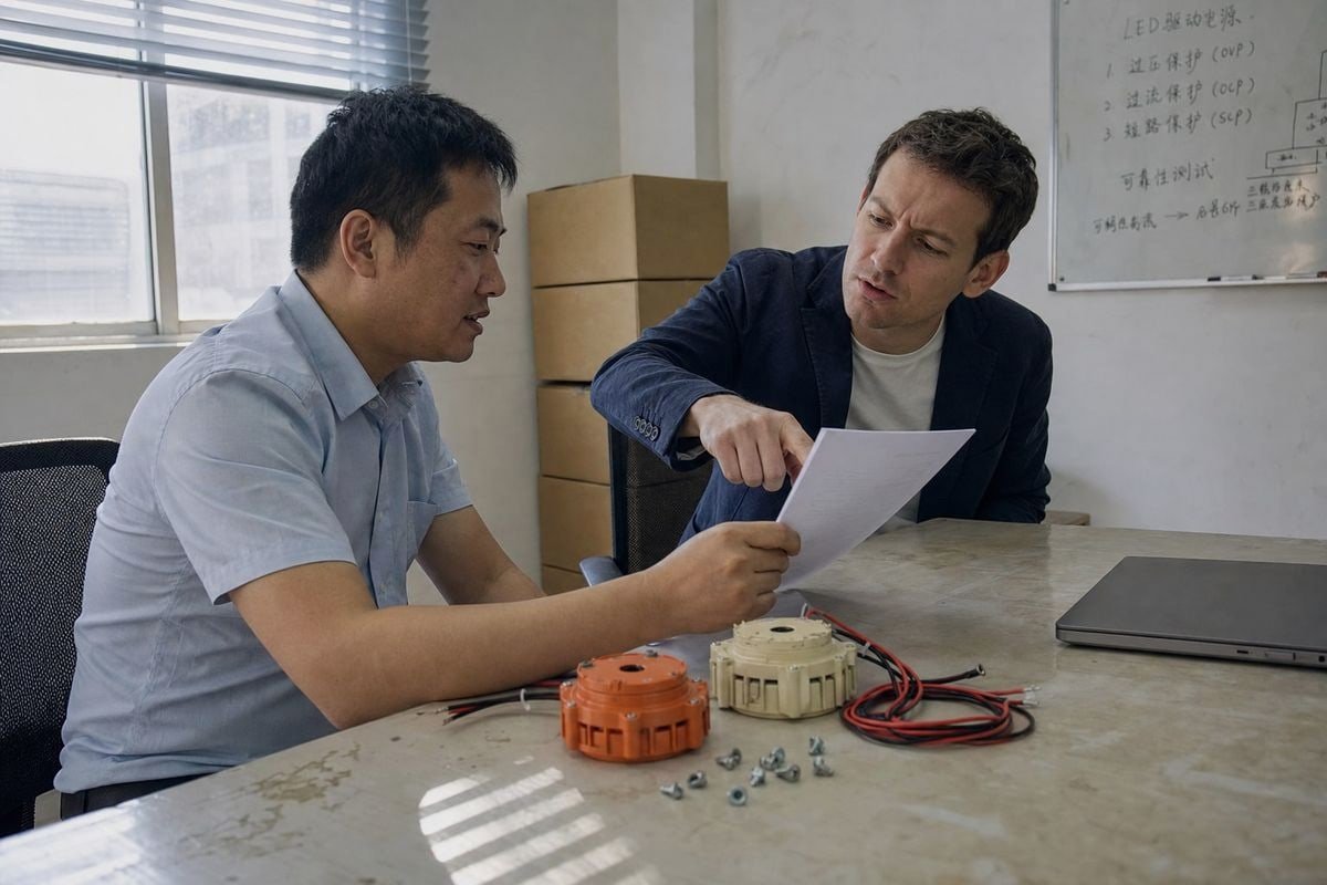
Seorang pembeli dari Prancis pernah mengirimkan kepada kami daftar spesifikasi lampu yang hanya mencantumkan daya dalam watt — tanpa menyebutkan arus maupun tegangan. Kami terpaksa mengembalikannya dengan satu pertanyaan: apa yang tertera dalam lembar data LED tersebut? Dokumen itu sendirilah yang menentukan segalanya.
Baca terlebih dahulu lembar spesifikasi LED. Jika arus penggerak disebutkan dalam mA atau A, pilihlah penggerak arus konstan yang sesuai persis dengan nilai tersebut. Jika tegangan operasi disebutkan dalam VDC, seperti 12V atau 24V, pilihlah penggerak tegangan konstan dengan cadangan daya yang memadai.
Ikuti proses pengambilan keputusan sederhana ini sebelum setiap pesanan pembelian:
- Periksa lembar spesifikasi LED. Arus dalam mA berarti CC. Tegangan dalam VDC berarti CV. Nilai daya saja tidak pernah cukup untuk menentukan keputusan.
- Periksa topologi kabel. Pemasangan seri versus paralel itu penting. Rangkaian chip atau modul LED COB yang dipasang secara seri memerlukan pengaturan arus konstan (CC). Modul dan strip yang dipasang secara paralel memerlukan pengaturan tegangan konstan (CV).
- Periksa rentang tegangan maju. Bagi pengguna driver CC, tegangan maju total rangkaian LED Anda harus berada di dalam rentang tegangan keluaran driver tersebut.
- Periksa antarmuka pengaturan kecerahan. Pastikan driver tersebut merupakan model CC yang dapat diredupkan 0–10 V atau model CV yang dapat diredupkan 0–10 V. Protokol peredupan tidak pernah menentukan jenis output.
- Periksa persyaratan kelas keselamatan. Pada banyak instalasi tegangan rendah, sebuah Catu daya Kelas 2 3 memudahkan kepatuhan dan pemeriksaan instalasi kabel.
Mengapa Pengkabelan Seri dan Paralel Penting
Sistem CC umumnya berbasis rangkaian seri. Setiap LED dalam rangkaian menerima arus yang sama, sehingga kecerahan tetap seragam di seluruh rangkaian. Sistem CV umumnya berbasis rangkaian paralel. Setiap modul atau segmen strip terhubung ke jalur tegangan yang sama, sehingga memudahkan penambahan atau penghilangan fixture saat terjadi perubahan tata letak. Berdasarkan pengalaman kami dalam mengekspor driver ke klien di Eropa, penggabungan kedua topologi ini merupakan penyebab utama kegagalan di lapangan. Beban paralel pada driver CC memaksa pembagian arus yang tidak merata. Rangkaian seri yang panjang pada driver CV tidak akan menyala dengan benar.
Memilih Berdasarkan Faktor Lain Selain Daya
Untuk pemilihan CC, pastikan nilai miliampere-nya sama persis — 350mA, 700mA, atau 1A adalah nilai-nilai yang paling umum kami kirimkan. Untuk pemilihan CV, pastikan kapasitas daya total driver melebihi jumlah total beban yang terhubung, idealnya dengan margin 20%. Menukar driver CC dan CV hanya karena daya yang sesuai adalah kesalahan yang sering kami temui, dan hal ini biasanya berakhir dengan lampu yang mati atau berkedip-kedip.
Faktor Biaya Apa Saja yang Harus Saya Pertimbangkan Saat Memilih Driver LED 0–10V untuk Produksi Skala Besar?
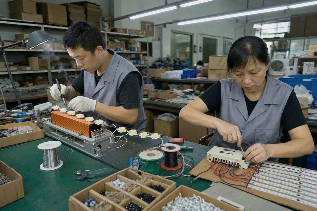
Ada pertimbangan yang selalu saya pertimbangkan setiap kali kami menyusun penawaran untuk pesanan dalam jumlah besar: harga satuan versus total biaya sistem. Komponen termurah yang tercantum dalam faktur jarang menjadi komponen termurah dalam produk jadi.
Untuk produksi skala besar, pertimbangkan biaya sistem secara keseluruhan, bukan harga satuan driver. Driver CV memang lebih murah per unit dan memudahkan tata letak paralel, namun driver CC dapat mengurangi tingkat kegagalan, klaim garansi, dan kerugian akibat pemasangan kabel. Pertimbangkan juga pemasangan kabel, ruang kosong, kualitas peredupan, dan persyaratan sertifikasi.
Berikut ini adalah rincian umum faktor-faktor biaya saat kami membantu klien menyusun anggaran proyek:
| Faktor Biaya | Dampak Arus Konstan | Dampak Tegangan Konstan |
|---|---|---|
| Harga satuan unit penggerak | Lebih tinggi per satuan | Lebih rendah per satuan |
| Pemasangan kabel dan instalasi kabel | Tahan terhadap penurunan tegangan pada jalur yang panjang | Penurunan tegangan mengharuskan penggunaan kabel yang lebih tebal atau jalur yang lebih pendek |
| Skalabilitas | Satu driver per fixture atau rangkaian | Satu driver besar dapat mengendalikan banyak modul paralel |
| Kegagalan dan risiko garansi | Lebih rendah; arus diatur | Akan lebih tinggi jika pembatasan arus pada sisi LED lemah |
| Biaya kualitas peredupan | CCR yang mulus, tanpa komponen tambahan | PWM mungkin memerlukan pengurangan efek berkedip untuk proyek-proyek kelas atas |
Biaya Tersembunyi dari Penurunan Tegangan
Penggerak CC secara otomatis menaikkan tegangan keluaran untuk mengatasi resistansi kabel. Hal itu membuatnya secara inheren kebal terhadap penurunan tegangan pada jalur yang panjang. Sistem CV tidak memiliki kelebihan tersebut. Pada instalasi strip 12V, kabel penghubung yang panjang dapat secara nyata membuat ujung terjauh dari rangkaian menjadi redup. Untuk mengatasinya, diperlukan tembaga yang lebih tebal, segmen yang lebih pendek, atau titik injeksi tambahan — yang semuanya membutuhkan biaya yang tidak sedikit pada skala produksi. Saat kami memberikan penawaran untuk proyek papan reklame berskala besar, ukuran kabel sering kali menjadi item yang paling mengejutkan pembeli.
Modularitas versus Perlindungan
Beberapa klien tidak setuju dan berpendapat bahwa CC selalu merupakan investasi yang lebih baik karena melindungi LED dan meningkatkan efisiensi. Yang lain bersikeras bahwa CV lebih unggul karena lebih murah dan lebih mudah dikonfigurasi ulang. Kedua pandangan tersebut setengah benar. Secara teknis, CC lebih disarankan untuk emitor telanjang dan perlengkapan berdaya tinggi. CV memang lebih ekonomis untuk produk tegangan rendah yang telah dirancang sebelumnya, di mana pembatas arus sudah terintegrasi di dalam modul. Beberapa pelanggan kami juga meminta driver hibrida CV+CC, yang beroperasi dalam mode tegangan konstan pada beban normal tetapi beralih ke mode arus konstan saat terjadi arus berlebih. Perlindungan hibrida tersebut memang sedikit lebih mahal di awal, tetapi mencegah kegagalan sistem yang parah — sebuah argumen yang kuat untuk instalasi komersial yang tidak diawasi.
Aplikasi mana yang paling cocok digunakan dengan sistem peredupan arus konstan dibandingkan sistem peredupan tegangan konstan 0–10 V?
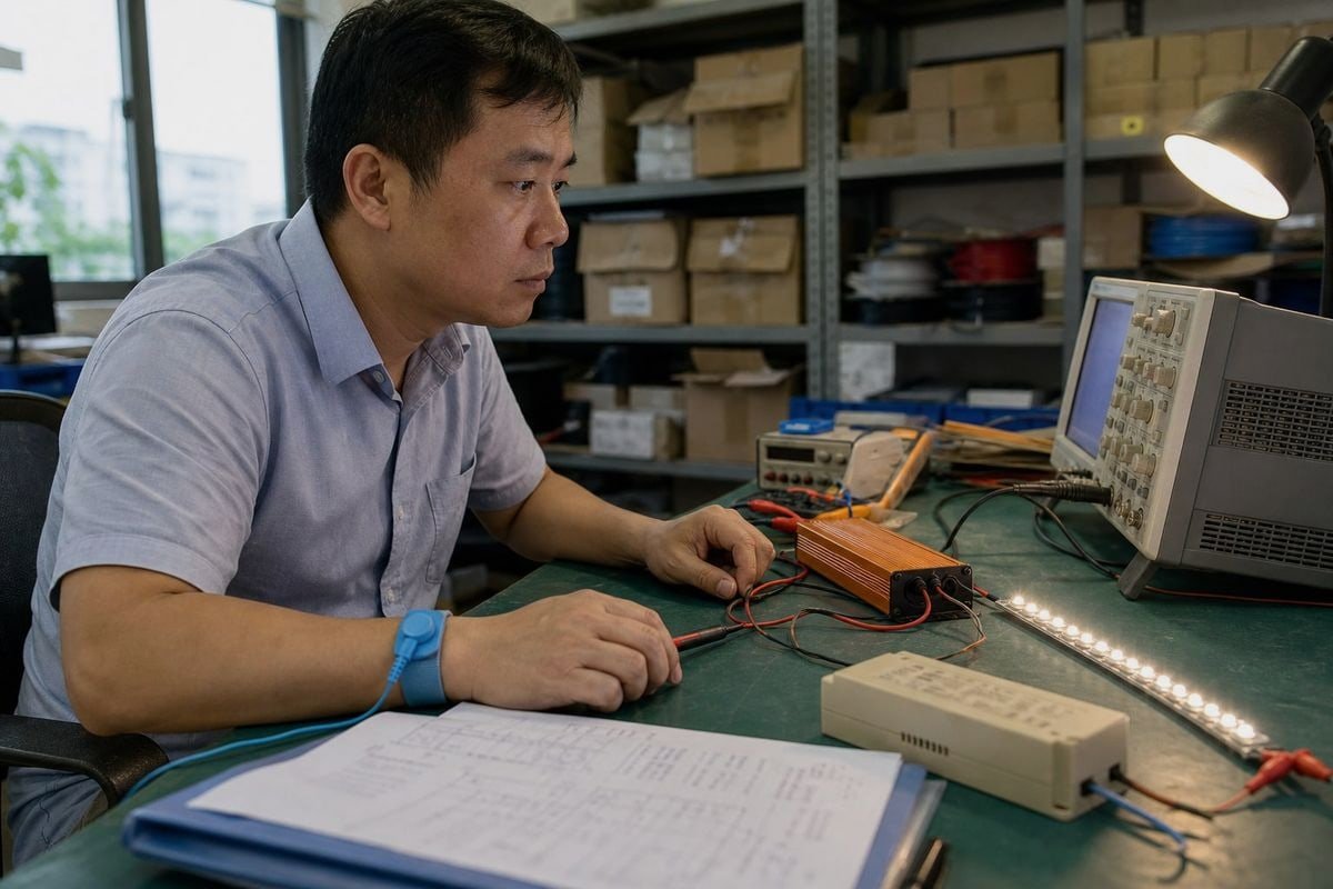
Di awal karier saya di sebuah pabrik lampu LED, saya menyaksikan sebuah pesanan lampu studio ditolak karena strip lampu tersebut berkedip saat direkam kamera. Lampu-lampu tersebut tampak sempurna jika dilihat dengan mata telanjang. Namun, sensor kamera tidak sependapat.
Driver arus konstan 0–10V paling cocok untuk lampu downlight, lampu panel, lampu high-bay, dan perlengkapan berbasis COB yang membutuhkan kecerahan seragam. Sistem tegangan konstan 0–10V cocok untuk lampu strip LED, papan reklame, pencahayaan cove, dan aplikasi aksen yang dibangun dari modul-modul yang disambungkan secara paralel.
Sesuaikan aplikasi dengan jenis driver menggunakan panduan ini:
| Aplikasi | Jenis yang Direkomendasikan | Mengapa |
|---|---|---|
| Lampu downlight dan lampu sorot yang tertanam | CC | Chip yang dihubungkan secara seri memerlukan arus yang tepat agar menghasilkan keluaran yang seragam |
| Lampu gantung tinggi dan lampu industri | CC | Pemancar berdaya tinggi memerlukan perlindungan terhadap arus berlebih |
| Pencahayaan untuk film dan siaran | CC dengan CCR frekuensi tinggi | Menghilangkan efek garis-garis yang terekam oleh sensor kamera berkecepatan tinggi |
| Lampu strip LED dan lampu pita | CV | Strip tersebut dilengkapi dengan resistor terintegrasi dan memerlukan tegangan 12V/24V yang stabil |
| Papan tanda dan huruf saluran | CV | Modul paralel mudah ditambahkan, dilepas, dan diganti |
| Pencahayaan sudut dan aksen | CV | Panjang yang fleksibel dan konfigurasi ulang di lapangan yang mudah |
Perilaku Peredupan pada Lampu Nyata
Kualitas peredupanlah yang menjadi pembeda utama antar aplikasi. Driver CC biasanya melakukan peredupan melalui metode Pengurangan Arus Konstan (Constant Current Reduction), yang menurunkan arus analog secara bertahap. Hal ini cocok untuk penerangan umum, dan sistem 0–10V yang dirancang dengan baik dapat meredupkan cahaya secara halus hingga 10%, 1%, dan bahkan 0,1% pada beberapa konfigurasi. Sistem CV lebih sering mengandalkan modulasi lebar pulsa (PWM), yang secara cepat mengubah siklus keluaran. PWM sangat cocok untuk sebagian besar pekerjaan dekoratif, tetapi PWM frekuensi rendah dapat menghasilkan kedipan yang terlihat 4 atau munculnya garis-garis pada gambar kamera. Untuk lingkungan video, CCR frekuensi tinggi pada driver CC merupakan spesifikasi yang lebih aman.
Kurva Peredupan dan Persepsi Manusia
Satu hal lagi yang menjadi perhatian para insinyur kami untuk proyek-proyek premium: bentuk kurva peredupan. Sebagian besar pengontrol 0–10V menghasilkan sinyal linier, namun mata manusia memandang cahaya secara non-linier. Driver CC kelas atas dapat diprogram dengan kurva peredupan logaritmik sehingga peredupan yang dirasakan terasa alami di seluruh rentang. Jika proyek Anda memerlukan kemampuan peredupan hingga mati total (dim-to-off), pastikan driver tersebut secara eksplisit mendukungnya — banyak driver 0–10V standar hanya dapat meredupkan hingga tingkat minimum dan tidak pernah benar-benar mati sepenuhnya tanpa relai terpisah.

Kesimpulan
Sesuaikan terlebih dahulu beban, baru kemudian sesuaikan metode peredupan. Jika LED Anda menentukan arus, pilih CC. Jika menentukan tegangan, pilih CV. Anggaplah rentang 0–10V semata-mata sebagai antarmuka peredupan — dan pastikan kompatibilitasnya sebelum memesan dalam jumlah besar.
Catatan kaki
- Menjelaskan metode peredupan teknis yang umumnya digunakan oleh driver CV untuk mengontrol kecerahan. ↩︎
- Latar belakang mengenai mode kegagalan akibat panas berlebih yang dapat dicegah oleh pengaturan arus konstan pada LED. ↩︎
- IEEE membahas klasifikasi keselamatan kelistrikan yang berkaitan dengan perancangan catu daya tegangan rendah. ↩︎
- ENERGY STAR memberikan panduan resmi mengenai standar kinerja kedipan pada produk pencahayaan LED. ↩︎