Skip to content










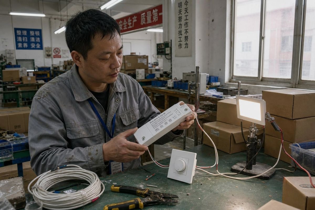
สัญญาณควบคุมในระบบลดแสง 0–10V สร้างความสับสนให้กับผู้ซื้อจำนวนมากที่ติดต่อโรงงานของเรา ไฟที่ไม่ดับ โซนที่กะพริบ ตัวลดแสงที่ไม่เข้ากัน — ปัญหาเหล่านี้ทำให้โปรเจกต์เสียทั้งเงินและเวลา.
การลดแสงแบบ 0–10V เป็นวิธีการควบคุมแสงแบบแอนะล็อกที่ใช้สัญญาณ DC แรงดันต่ำ ซึ่งทำงานบนสายคู่แยก เพื่อบอกให้ไดรเวอร์ LED ที่เข้ากันได้ผลิตแสงในปริมาณเท่าใด 10V สั่งให้เอาต์พุตเต็มที่ แรงดันที่ต่ำกว่าจะลดความสว่างลง และ 0V หมายถึงเอาต์พุตขั้นต่ำหรือปิด ขึ้นอยู่กับการออกแบบของไดรเวอร์.
คำตอบสั้นๆ นั้นซ่อนรายละเอียดไว้มากมาย ด้านล่างนี้ ผมจะอธิบายว่าสัญญาณทำงานอย่างไร วิธีจับคู่อุปกรณ์ ทำไมระบบถึงกะพริบ และวิธีเดินสายและแก้ไขปัญหาอย่างถูกต้อง.
สัญญาณควบคุม 0-10V คืออะไรกันแน่ และมันทำงานอย่างไร?
ระหว่างการปรับเทียบไดรเวอร์ที่สายการผลิต boqi ของเราเมื่อปีที่แล้ว วิศวกรใหม่คนหนึ่งถามผมว่าทำไมไฟถึงกระโดดไปที่ความสว่างเต็มที่ทันทีที่เขาถอดสายสีม่วง คำถามนั้นจับใจความสำคัญของตรรกะทั้งหมดของสัญญาณควบคุมแบบแอนะล็อกนี้ได้.
สัญญาณควบคุม 0-10V คือแรงดันไฟฟ้ากระแสตรงที่ส่งผ่านสายไฟแรงดันต่ำสองเส้นโดยเฉพาะ แยกจากไฟหลัก ไดรเวอร์ LED จะอ่านระดับแรงดันไฟฟ้าและปรับแสงเอาต์พุตตามนั้น: 10V เท่ากับ 100%, 5V เท่ากับประมาณ 50% และ 0V เท่ากับเอาต์พุตขั้นต่ำหรือปิด ขึ้นอยู่กับไดรเวอร์.
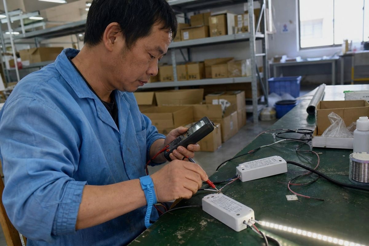
ประเด็นสำคัญคือการแยกออกจากกัน ระบบ 0–10V ไม่ได้ตัดแรงดันไฟฟ้าหลักแบบที่ ตัวลดแสง TRIAC แบบตัดเฟส ทำ แต่วงจรไฟฟ้าจ่ายไฟให้ไดรเวอร์ที่แรงดัน mains เต็มรูปแบบ ในขณะที่ วงจรลดแสงแรงดันต่ำ 1 แยกต่างหากเป็นตัวนำคำสั่ง ไดรเวอร์ตีความคำสั่งนั้นภายใน โดยมักจะแปลงระดับแอนะล็อกเป็น Pulse Width Modulation หรือการลดกระแสคงที่ในฝั่ง LED.
แรงดันไฟฟ้าแมปกับความสว่างอย่างไร
นี่คือแผนผังแบบย่อทั่วไปที่เราพิมพ์ในเอกสารข้อมูลไดรเวอร์ของเรา ให้ถือเป็นกฎคร่าวๆ ไม่ใช่กฎสากล เพราะเส้นโค้งการลดแสงจริงขึ้นอยู่กับการตั้งโปรแกรมของไดรเวอร์.
| แรงดันควบคุม | เอาต์พุตแสงโดยทั่วไป | หมายเหตุ |
|---|---|---|
| 10V (หรือสูงกว่า) | 100% | สัญญาณที่สูงกว่า 10V อิ่มตัวที่ระดับสูงสุด ตามคำแนะนำของ Lutron |
| 7–8V | ~75% | ค่าประมาณ ขึ้นอยู่กับเส้นโค้ง |
| 5V | ~50% | จุดอ้างอิงที่ถูกกล่าวถึงมากที่สุด |
| 3V | ~25% | ค่าประมาณ ขึ้นอยู่กับเส้นโค้ง |
| 1V | ระดับต่ำสุดที่ใช้งานได้ | ค่าพื้นทั่วไปในระบบ 1–10V |
| 0V | ขั้นต่ำหรือปิด | พฤติกรรมขึ้นอยู่กับไดรเวอร์ |
พฤติกรรมค่าเริ่มต้นไปที่ความสว่างเต็มที่
เมื่อสายควบคุมเปิดวงจร — ถอดออกหรือขาด — ไดรเวอร์สมัยใหม่ส่วนใหญ่จะตั้งค่าเป็น 10V ภายในและทำงานที่เอาต์พุต 100% หรือใกล้เคียง ซึ่งตั้งใจให้เป็นเช่นนี้ การเปิดวงจรในสายควบคุมทำหน้าที่เป็นระบบความปลอดภัยแบบ fail-safe ทำให้ไฟยังคงติดอยู่แทนที่จะทำให้คลังสินค้ามืดลง ในทางกลับกัน การลัดวงจรสายควบคุมสองเส้นเข้าด้วยกันจะดึงสัญญาณไปที่ 0V และบังคับให้ไฟไปที่ระดับลดแสงขั้นต่ำ.
0–10V เทียบกับ 1–10V: ความแตกต่างที่ทำให้เกิดความสับสน
ป้ายสองแบบนี้ใช้แทนกันไม่ได้ แนวทาง 1–10V ย้อนกลับไปที่ IEC 60929 Annex E ซึ่งเดิมเขียนขึ้นสำหรับ บัลลาสต์ฟลูออเรสเซนต์ 2, ซึ่งไฟจะหยุดที่ระดับแสงต่ำและไม่สามารถปิดผ่านอินพุตลดแสงเพียงอย่างเดียว ในระบบ 0–10V ไดรเวอร์บางตัวสามารถปิดได้จริง แต่ผลิตภัณฑ์หลายตัวยังต้องใช้รีเลย์แยกหรือฟังก์ชันสวิตช์เพื่อปิดสนิท จากประสบการณ์ของเราในการจัดส่งไดรเวอร์ LED แบบลดแสง 0-10V ไปยังยุโรปและเอเชียตะวันออกเฉียงใต้ ความคลุมเครือที่ปลายล่างนี้คือสเปกที่เข้าใจผิดมากที่สุดในเอกสารข้อมูลใดๆ.
ฉันจะเลือกตัวหรี่ไฟ 0-10V ที่เหมาะสมสำหรับไดรเวอร์ LED ของฉันได้อย่างไร?
ลูกค้าตัวแทนจำหน่ายจากสิงคโปร์เคยส่งรูปตัวลดแสงที่เขาหามาจากที่อื่นมาให้เรา ซึ่งไม่สามารถลดแสงไดรเวอร์ของเราต่ำกว่า 40% ได้ ความไม่เข้ากันไม่ใช่เรื่องคุณภาพ — แต่เป็น พฤติกรรมการจมและจ่ายกระแส, ซึ่งเป็นรายละเอียดที่ซัพพลายเออร์เดิมของเขาไม่เคยอธิบาย.
เลือกตัวลดแสง 0-10V โดยยืนยันสามสิ่ง: ตรงกับโทโพโลยี sink หรือ source ของไดรเวอร์ ความสามารถในการจมกระแสครอบคลุมกระแสรั่วไหลรวมของทุกไดรเวอร์ในโซน และเส้นโค้งการลดแสงเหมาะกับการใช้งาน ตรวจสอบความเข้ากันได้ของไดรเวอร์ LED จากเอกสารข้อมูลทั้งสองก่อนซื้อ.

ไดรเวอร์ LED สมัยใหม่ส่วนใหญ่ทำหน้าที่เป็นแหล่งจ่ายกระแส ไดรเวอร์เองจ่ายกระแสขนาดเล็กที่สูงถึง 10V บนสายควบคุม และตัวลดแสงติดผนังทำหน้าที่เป็นตัวจมกระแส ดึงแรงดันนั้นลงไปยังระดับที่ต้องการ นี่คือเหตุผลที่ตัวลดแสงและไดรเวอร์บางตัวใช้แทนกันไม่ได้แม้ทั้งคู่จะมีป้าย “0–10V” ตัวลดแสงแบบ source จับคู่กับไดรเวอร์แบบ source จะต่อสู้กันเอง และผลลัพธ์คือการลดแสงที่ผิดปกติหรือไม่ทำงานเลย.
ปัญหาความสามารถในการจมกระแสในโซนขนาดใหญ่
ไดรเวอร์แต่ละตัวรั่วกระแสเล็กน้อยลงบนบัสควบคุม ในการติดตั้งที่มีความหนาแน่นสูง — เช่นคลังสินค้าเพดานสูงที่มีไฟหกสิบดวงในโซนเดียว — กระแสรั่วไหลสะสม กระแสรั่วไหล 3 อาจเกินความสามารถในการจมกระแสของคอนโทรลเลอร์ เมื่อเกิดเหตุการณ์นั้น อาร์เรย์จะไม่มีทางถึงระดับ 1% ขั้นต่ำหรือเกณฑ์การปิดได้ ไม่ว่าคุณจะเลื่อนแถบเลื่อนไปที่ใด ก่อนที่เราจะเสนอราคาโปรเจกต์ ทีมสนับสนุนเทคนิคของเราจะถามจำนวนไฟต่อโซนเพื่อตรวจสอบตัวเลขนี้โดยเฉพาะ.
รายการตรวจสอบการเลือกที่ใช้งานได้จริง
- ยืนยันโทโพโลยีการควบคุมของไดรเวอร์ (sink หรือ source) บนเอกสารข้อมูล.
- ตรวจสอบกระแสจมสูงสุดของตัวลดแสงเทียบกับกระแสรั่วไหลรวมของไดรเวอร์.
- ยืนยันระดับการลดแสงขั้นต่ำของไดรเวอร์ — 10%, 1% หรือฟังก์ชันปิดเมื่อลดแสง.
- ตัดสินใจว่าคุณจำเป็นต้องมีรีเลย์ในตัวสำหรับการปิดไฟเต็มรูปแบบหรือไม่.
- จับคู่เส้นโค้งการหรี่แสง (เชิงเส้นเทียบกับลอการิทึม) ให้เข้ากับพื้นที่.
อ่านสเปกชีตอย่างถูกวิธี
| รายการในสเปกชีต | สิ่งที่บอกคุณ | เหตุผลที่สำคัญ |
|---|---|---|
| ช่วงการหรี่แสง (เช่น 10–100%, 1–100%) | ค่าผลลัพธ์ต่ำสุดจริง | กำหนดว่า 0V หมายถึงปิดหรือแค่หรี่แสง |
| กระแสซิงก์ต่อไดรเวอร์ (เช่น 0.5mA) | โหลดบนบัสควบคุม | คูณด้วยจำนวนโคมไฟเพื่อคำนวณขนาดโซน |
| ประเภทเส้นโค้งการหรี่แสง | การตอบสนองเชิงเส้นหรือลอการิทึม | ส่งผลต่อความนุ่มนวลที่รับรู้ได้ |
| การรองรับการหรี่จนปิดสนิท | ว่า 0V ตัดแสงได้เต็มที่หรือไม่ | หลีกเลี่ยงข้อร้องเรียนเรื่อง “ปิดไม่สนิท” |
ดวงตามนุษย์รับรู้ความสว่างแบบลอการิทึม ไดรเวอร์ที่มีเส้นโค้งการหรี่แสงเชิงเส้นล้วนสร้างโซน “การเลื่อนที่ไร้ผล” ซึ่งแสงดูไม่เปลี่ยนแปลงในช่วงประมาณ 30% แรกของการเลื่อนแถบเลื่อน สำหรับโครงการโรงแรมและที่พักอาศัย เราแนะนำไดรเวอร์ที่มีเส้นโค้งลอการิทึม สำหรับโซนอุตสาหกรรม เชิงเส้นมักจะยอมรับได้.
ทำไมระบบปรับแสง 0-10V ของฉันถึงกะพริบหรือปรับแสงไม่ราบรื่น?
ใบแจ้งปัญหาการสนับสนุนที่ยุ่งยากที่สุดที่ฉันเคยจัดการเกี่ยวข้องกับการปรับปรุงไฟถนนในเวียดนามที่โคมไฟทุกดวงกะพริบตอนพลบค่ำ — แต่เฉพาะตอนพลบค่ำเท่านั้น สาเหตุกลายเป็นแรงดันเหนี่ยวนำบน สายควบคุมที่ไม่มีฉนวนหุ้ม 4 ที่วิ่งขนานไปกับสายไฟหลัก.
การกะพริบและการหรี่แสงที่ไม่ราบรื่นในระบบ 0-10V มักเกิดจากการรบกวนทางแม่เหล็กไฟฟ้าที่เหนี่ยวนำแรงดันไฟฟ้าหลอกบนสายควบคุมที่ไม่มีฉนวนหุ้ม แรงดันตกคร่อมตามสายโซ่เดซี่ที่ยาว การแปลง PWM ที่มีความละเอียดต่ำภายในไดรเวอร์ หรือคอนโทรลเลอร์ที่รับโหลดเกินจนไม่สามารถดูดซับกระแสไฟฟ้าได้เพียงพอสำหรับโซนนั้น.
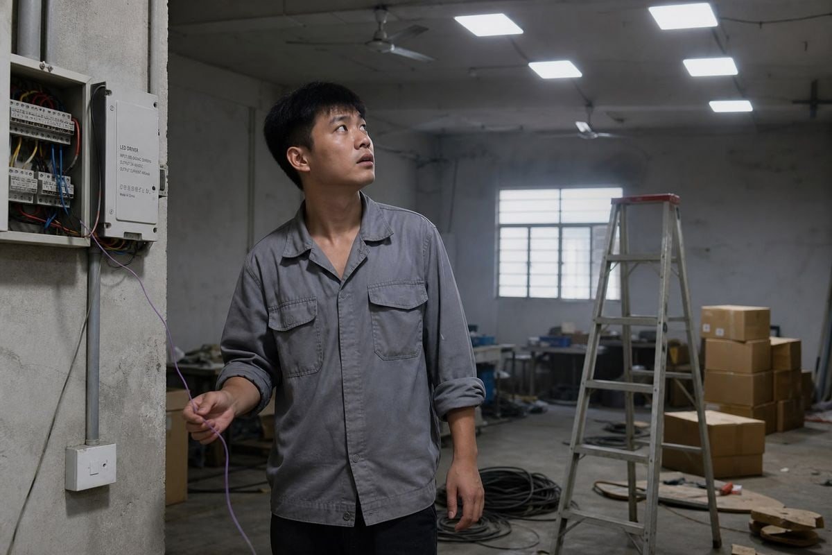
เนื่องจากอินพุตควบคุมเป็นสัญญาณแอนะล็อกอิมพีแดนซ์ต่ำ จึงเสี่ยงต่อปัญหาในแบบที่ โปรโตคอลดิจิทัลเช่น DALI ไม่เป็นเช่นนั้น ให้ฉันอธิบายสาเหตุทั่วไปสี่ประการที่เราวินิจฉัยให้กับบริษัทวิศวกรรมและโรงงานผลิตไฟ.
การรบกวนทางแม่เหล็กไฟฟ้าและแรงดันผี
ความสมบูรณ์ของสัญญาณไวต่อ EMI อย่างมาก การเดินสายควบคุมที่ไม่มีฉนวนขนานกับสายไฟฟ้าแรงสูงสามารถเหนี่ยวนำแรงดันผีบนคู่สายควบคุม ซึ่งไดรเวอร์ตีความว่าเป็นคำสั่งความสว่าง ผลลัพธ์คือการกะพริบที่มองเห็นได้ โดยเฉพาะที่ระดับการหรี่ต่ำซึ่งไม่กี่ร้อยมิลลิโวลต์หมายถึงการเปลี่ยนแปลงเป็นเปอร์เซ็นต์ที่มีนัยสำคัญ สำหรับระยะทางไกล คู่สายตีเกลียวมีฉนวนหุ้มพร้อมการต่อกราวด์ที่ปลายด้านหนึ่งคือวิธีแก้ไข.
แรงดันตกตามระยะทาง
ปัญหาแรงดันตกมักเกิดกับโซนที่ต่อแบบเดซี่เชนขนาดใหญ่ ตัวเลขทั่วไปคือแรงดันตก 1V ถึง 2V ต่อสายยาว 1,000 ฟุต นั่นหมายความว่าโคมไฟดวงแรกในโซ่อาจเห็น 5V ในขณะที่ดวงสุดท้ายเห็น 3.5V — ระดับความสว่างที่แตกต่างอย่างเห็นได้ชัด ในโครงการคลังสินค้าขนาดใหญ่หรือไฟถนน เราแนะนำสายควบคุมที่ใหญ่ขึ้น ระยะทางสั้นลง หรือแบ่งโซน.
การลดลงเป็นขั้นบันไดที่ระดับต่ำ
หากแสงหรี่ลงเป็นขั้นที่มองเห็นได้แทนที่จะค่อยๆ ลดลงอย่างนุ่มนวล สาเหตุมักมาจากการแปลง Pulse Width Modulation ความละเอียดต่ำภายในไดรเวอร์ สัญญาณแอนะล็อกถูกแปลงเป็นขั้นดิจิทัลที่ไม่ต่อเนื่อง และตัวแปลงราคาถูกใช้ขั้นตอนเหล่านี้น้อยเกินไป นี่คือปัญหาคุณภาพไดรเวอร์ ไม่ใช่ปัญหาการเดินสาย และเป็นหนึ่งในเหตุผลที่ไดรเวอร์ระดับกลางถึงสูงของเราใช้การแปลงภายในที่มีความละเอียดสูงกว่า.
ปรากฏการณ์ป๊อปคอร์นกับบริดจ์ไร้สาย
การปรับปรุงระบบในปัจจุบันใช้ตัวควบคุมบริดจ์ไร้สายเป็นแอนะล็อกมากขึ้น ความหน่วงในบริดจ์เหล่านี้อาจทำให้เกิดปรากฏการณ์ป๊อปคอร์น ซึ่งโคมไฟในโซน 0–10V เดียวกันเปิดหรือเปลี่ยนความเข้มในเวลาที่ต่างกันเล็กน้อยเนื่องจากความหน่วงในการประมวลผล เป็นเรื่องด้านความสวยงาม แต่ลูกค้าสังเกตเห็นในล็อบบี้และพื้นที่ค้าปลีก.
ฉันจะเดินสายและแก้ไขปัญหาสัญญาณควบคุม 0-10V ในโปรเจกต์ของฉันได้อย่างไร?
บทเรียนหนึ่งที่ทีมส่งออกของเราเรียนรู้ตั้งแต่แรก: ธรรมเนียมการเดินสายแตกต่างกันตามตลาด และการสมมติว่าช่างติดตั้งรู้รหัสสีเป็นความผิดพลาด ตอนนี้เราใส่การ์ดคำแนะนำการเดินสายในทุกกล่องที่เราจัดส่งไปออสเตรเลียและสหภาพยุโรป.
เดินสายสัญญาณควบคุม 0-10V โดยใช้สายสีม่วงสำหรับ DIM+ และสายสีชมพูหรือสีเทาสำหรับ DIM- ร่วม โดยรักษาขั้วให้ถูกต้อง เดินคู่สายแยกจากสายไฟหลักหากเป็นไปได้ และแก้ไขปัญหาด้วยมัลติมิเตอร์โดยวัดแรงดัน DC โดยตรงที่ขั้วควบคุมของไดรเวอร์.
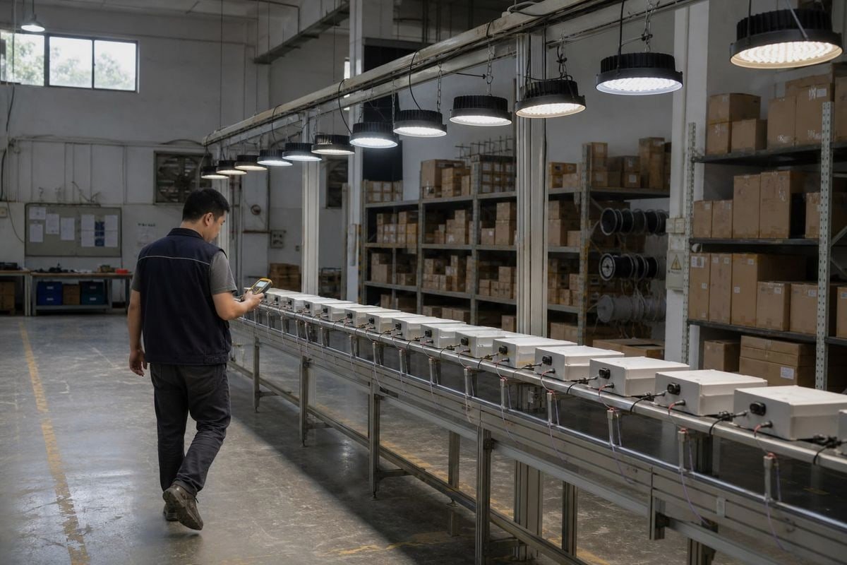
การเดินสายทางกายภาพดูง่าย — สายเส้นเล็กสองเส้น — แต่อินเทอร์เฟซควบคุมแสงนี้มีกฎจริงเบื้องหลัง หากทำผิด คุณจะเจอทุกปัญหาที่กล่าวถึงข้างต้น.
สีสายไฟ ขั้ว และการจำแนกประเภทตามรหัส
ธรรมเนียมอุตสาหกรรมคือสีม่วงสำหรับ DIM+ และสีเทาหรือสีชมพูสำหรับ DIM- มาตรฐานอุตสาหกรรมได้เปลี่ยนสายรองจากสีเทาไปเป็นสีชมพูเพื่อป้องกันความสับสนอันตรายกับสายนิวทรัลสีเทาที่ใช้ในวงจร 277V AC สัญญาณไวต่อขั้วในทางปฏิบัติ ดังนั้นการกลับขั้วบนไดรเวอร์แบบซิงก์มักทำให้โคมไฟติดค้างที่ความสว่างเต็มที่.
ยังมีมิติด้านรหัสที่ผู้ซื้อหลายคนมองข้าม แม้ว่า 0–10V จะเป็นสัญญาณแรงดันต่ำที่ปกติจัดอยู่ใน มาตรฐานการเดินสาย Class 2 5, แต่ต้องจัดประเภทใหม่เป็น Class 1 ด้วยฉนวนที่ทนแรงดัน 600V หากสายควบคุมใช้ท่อร้อยสายหรือกล่องรวมสายร่วมกับสายไฟแรงดันหลัก เราระบุระดับฉนวนบนสายนำของไดรเวอร์ด้วยเหตุผลนี้พอดี.
ขั้นตอนการแก้ไขปัญหาทีละขั้น
| อาการ | สาเหตุที่เป็นไปได้ | สิ่งที่ต้องตรวจสอบ |
|---|---|---|
| ติดค้างที่ความสว่างเต็มที่ | คู่สายควบคุมเปิดหรือกลับขั้ว | ความต่อเนื่องของสายสีม่วง/สีชมพู; ขั้วที่ไดรเวอร์ |
| ค้างอยู่ที่ระดับต่ำสุด | คู่ควบคุมลัดวงจร | ความต้านทานระหว่าง DIM+ และ DIM- |
| จะไม่ปิดสนิท | ไดรเวอร์มีค่าต่ำสุดพื้นฐาน ไม่มีรีเลย์ | ช่วงการหรี่แสงตาม datasheet; เพิ่มรีเลย์สลับ |
| ความสว่างไม่สม่ำเสมอในโซน | แรงดันตกในระยะทางยาว | แรงดัน DC ที่โคมแรกเทียบกับโคมสุดท้าย |
| กระพริบแบบสุ่ม | EMI หรือซิงก์ที่รับโหลดเกิน | การเดินสายไฟ; การรั่วไหลรวมเทียบกับความจุของตัวหรี่แสง |
เมื่อลูกค้าส่งรายงานข้อบกพร่องมา กระบวนการสนับสนุนของเราจะเหมือนเดิมเสมอ: วัดแรงดัน DC ที่ขั้วไดรเวอร์ก่อน ไม่ใช่ที่ตัวหรี่แสง หากไดรเวอร์เห็นแรงดันที่ถูกต้องแต่ทำงานผิดปกติ แสดงว่าปัญหาอยู่ที่ไดรเวอร์หรือการตั้งค่า dim-to-off หากแรงดันที่ไดรเวอร์ต่างจากเอาต์พุตของตัวหรี่แสง แสดงว่าสายไฟ — แรงดันตก การลัดวงจร การรบกวน หรือขั้วกลับ — เป็นต้นเหตุ นิสัยข้อนี้ช่วยแก้ปัญหาส่วนใหญ่ในหน้างานได้ภายในหนึ่งวันผ่าน WhatsApp ซึ่งสำคัญมากเมื่อช่างติดตั้งของคุณยืนอยู่บนลิฟต์รอคำตอบ.

บทสรุป
การหรี่แสงแบบ 0–10V ยังคงเป็นที่นิยมเพราะง่าย ถูก และพิสูจน์แล้ว — แต่เฉพาะเมื่อสัญญาณควบคุมแบบอนาล็อก พฤติกรรมของไดรเวอร์ และการเดินสายไฟจับคู่กันอย่างถูกต้อง ทำให้สามอย่างนี้ถูกต้อง มันก็ทำงานได้ทันที.
เชิงอรรถ
- IEEE ให้มาตรฐานทางเทคนิคสำหรับสัญญาณอิเล็กทรอนิกส์แรงดันต่ำและวงจรควบคุม. ↩︎
- Energy.gov ให้ข้อมูลครอบคลุมเกี่ยวกับระบบไฟแบบเก่าและการเปลี่ยนไปใช้ LED. ↩︎
- Wikipedia อธิบายคุณสมบัติทางไฟฟ้าของกระแสที่หลุดออกจากเส้นทางที่ตั้งใจไว้ในวงจร. ↩︎
- Wikipedia อธิบายโครงสร้างและคุณสมบัติการรบกวนของสายไฟประเภทต่างๆ. ↩︎
- OSHA กำหนดข้อกำหนดด้านความปลอดภัยสำหรับการจำแนกการเดินสายไฟฟ้าและระดับฉนวน. ↩︎