Skip to content










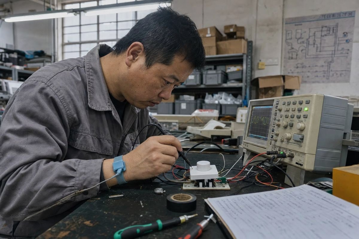
ผู้ซื้อถามผมเกี่ยวกับการหรี่ไฟแบบ TRIAC เกือบทุกสัปดาห์ในสายการผลิตของเรา หลายคนจับคู่ไดม์เมอร์ผิดกับไดรเวอร์ผิด ดูไฟกระพริบที่หน้างาน แล้วโทษไฟ LED ความสับสนนั้นทำให้โปรเจกต์เสียเงินจริง — และทั้งหมดเริ่มต้นจากคำถามที่เข้าใจผิดเพียงข้อเดียว.
TRIAC dimming เป็นวิธีการปรับความสว่างแบบ AC วิธีหนึ่ง ตัวหรี่ไฟแบบ TRIAC จะตัดเฟสของรูปคลื่นไฟฟ้ากระแสสลับหลัก โดยเปิดสวิตช์ที่จุดที่เลือกในแต่ละครึ่งรอบเพื่อลดกำลังไฟฟ้าที่ส่งออก วิธีนี้ไม่ได้ปรับแรงดัน DC โดยตรง แม้ว่าไดรเวอร์ LED ที่เข้ากันได้อาจแปลงไฟฟ้ากระแสสลับที่ถูกตัดเป็น DC ภายในก็ตาม.
พูดง่ายๆ: การหรี่ไฟแบบ TRIAC = ไฟ AC + การตัดเฟส แต่คำตอบสั้นๆ นั้นซ่อนปัญหาที่ลึกกว่า ให้ผมอธิบายสิ่งที่เกิดขึ้นจริงระหว่างไดม์เมอร์กับไฟ LED ของคุณ และทำไมมันถึงสำคัญต่อโปรเจกต์ของคุณ.
TRIAC การหรี่แสงควบคุมแรงดันไฟฟ้ากระแสสลับในโปรเจกต์ไฟของฉันได้อย่างไรจริงๆ?
เมื่อเราปรับเทียบไดม์เมอร์ TRIAC ที่โรงงาน boqi เราดูคลื่น ไซน์เวฟ 1 บนออสซิลโลสโคป รูปคลื่นนั้นบอกเรื่องราวทั้งหมดว่าเทคโนโลยีนี้ทำงานอย่างไร.
วงจรหรี่ไฟแบบ TRIAC จะหน่วงการนำกระแสภายในแต่ละครึ่งรอบของไฟฟ้ากระแสสลับ จากนั้นจะสลับเปิดและนำกระแสจนกระทั่งกระแสข้ามศูนย์ การจุดชนวน TRIAC เร็วขึ้นจะส่งคลื่นไซน์และแสงมากขึ้น การจุดชนวนช้าลงจะตัดคลื่นออกมากขึ้นและหรี่แสงลง.

คำว่า TRIAC ย่อมาจาก Triode for Alternating Current ชื่อนั้นยืนยันแล้วว่ามันเป็นอุปกรณ์ AC มันคือ ไทริสเตอร์แบบสองทิศทาง 2, ซึ่งหมายความว่ามันนำกระแสได้ทั้งสองทิศทาง ดังนั้นมันจึงทำงานทั้งในช่วงครึ่งบวกและครึ่งลบของรอบ AC นี่คือการทำงานพื้นฐานของไทริสเตอร์ และนี่คือเหตุผลที่ TRIAC กลายเป็นมาตรฐานการหรี่ไฟในที่อยู่อาศัยที่โดดเด่น: มันทำงานกับสายไฟ AC สองเส้นที่มีอยู่โดยไม่ต้องมีสายควบคุมเฉพาะ.
หลักการตัดเฟส ทีละขั้นตอน
นี่คือลำดับที่เกิดขึ้นซ้ำ 100 หรือ 120 ครั้งต่อวินาทีบนแหล่งจ่าย 50/60Hz:
- แรงดัน AC ข้ามศูนย์และ TRIAC ปิดตัวเองตามธรรมชาติ.
- วงจรจับเวลาภายในไดม์เมอร์รอการหน่วงเวลาที่ตั้งไว้ ปุ่มหมุนของคุณปรับการหน่วงเวลานี้.
- เกตยิง TRIAC ล็อกเปิด และกระแสไหลไปยังโหลด.
- กระแสลดลงเป็นศูนย์ที่จุดข้ามถัดไป และรอบนั้นเกิดขึ้นซ้ำ.
สิ่งนี้เรียกว่าการหรี่แบบตัดเฟส หรือการควบคุมมุมเฟส ไดม์เมอร์ TRIAC แบบดั้งเดิมใช้การควบคุมแบบ leading-edge หรือเรียกอีกอย่างว่า การหรี่แบบ forward phase 3, ซึ่งตัดจุดเริ่มต้นของแต่ละครึ่งรอบ การตัดส่วนหน้าของคลื่นจะลดแรงดัน RMS ที่ไปถึงโหลด.
สิ่งที่โหลดได้รับจริง
| จุดยิงในครึ่งรอบ | ส่วนของรูปคลื่นที่ส่งถึง | ระดับแสง |
|---|---|---|
| เร็วมาก (ใกล้ 0°) | เกือบเต็มไซน์เวฟ | ใกล้ความสว่าง 100% |
| กลาง (ประมาณ 90°) | ประมาณครึ่งหนึ่งของรูปคลื่น | ความสว่างปานกลาง |
| ช้า (ใกล้ 150°+) | ส่วนเล็กๆ ของรูปคลื่น | ระดับหรี่ลึก |
สังเกตสิ่งที่ไม่ได้เกิดขึ้นที่นี่ แหล่งจ่ายไม่เคยกลายเป็น DC โหลดเพียงแค่ได้รับพลังงาน AC เฉลี่ยน้อยลงเพราะส่วนหนึ่งของแต่ละไซน์เวฟถูกตัดออกไป การตรวจจับจุดข้ามศูนย์คือสิ่งที่ทำให้ระบบทั้งหมดทำงาน เพราะ TRIAC อาศัยกระแสที่ลดลงเป็นศูนย์ตามธรรมชาติเพื่อปิด การปรับรูปคลื่นไซน์แบบนี้เป็นเทคนิค AC โดยพื้นฐานตั้งแต่ต้นจนจบ.
ฉันสามารถใช้ไดม์เมอร์ TRIAC กับไดรเวอร์ LED ที่ใช้ไฟ DC ได้อย่างปลอดภัยหรือไม่?
ผู้ซื้อจากสิงคโปร์เคยถามผมว่าทำไมไดม์เมอร์ TRIAC ของเขาถึงล็อกเปิดค้างเมื่อต่อกับวงจร DC คำตอบนั้นสอนทีมของเขาบทเรียนที่วิศวกรของเรารู้ขึ้นใจ.
ไม่ — ไดม์เมอร์ TRIAC ต้องอยู่ฝั่ง AC ห้ามอยู่บนสาย DC เด็ดขาด TRIAC อาศัยการข้ามศูนย์ของ AC เพื่อปิด; กับ DC ที่คงที่ไม่มีจุดข้ามศูนย์ ดังนั้น TRIAC จะล็อกเปิดถาวร ใช้ไดม์เมอร์ TRIAC กับไดรเวอร์ที่ออกแบบมาสำหรับอินพุต AC แบบตัดเฟสเท่านั้น.

นี่คือจุดที่คำถาม “AC หรือ DC” น่าสนใจจริงๆ สำหรับโปรเจกต์ LED ตัว LED เองเป็นอุปกรณ์ที่ใช้ DC โดยธรรมชาติ มันทำงานกับกระแสตรงที่ควบคุม โดยปกติจากไดรเวอร์กระแสคงที่ แต่การหรี่แบบ TRIAC ยังทำงานกับ LED ได้ — ตราบใดที่เส้นทางสัญญาณถูกต้อง.
เส้นทางสัญญาณจริงในระบบ LED แบบหรี่ได้
นี่คือวิธีที่ระบบ TRIAC แบบหรี่ได้ที่ออกแบบอย่างถูกต้องไหล:
ไฟหลัก AC → รูปคลื่นตัดเฟส TRIAC → อินพุตไดรเวอร์ LED → วงจรบริดจ์เรกติไฟเออร์ / บัส DC → การควบคุมกระแส LED → ไฟ LED
TRIAC ควบคุมรูปคลื่นอินพุต AC จากนั้นไดรเวอร์จะเรกติไฟ รูปคลื่นที่ผิดเพี้ยน 4, กรองมัน และควบคุมกระแส DC ที่สะอาดสำหรับ LED ข้อมูลการหรี่เดินทางเป็นมุมเฟสบนฝั่ง AC และอัลกอริทึมการหรี่ของไดรเวอร์แปลมุมนั้นเป็นเอาต์พุต DC ตามสัดส่วน ดังนั้นคำกล่าวที่ว่า “การหรี่แบบ TRIAC เป็น AC” ไม่ได้หมายความว่า LED ทำงานโดยตรงจาก AC การเรกติไฟเกิดขึ้นทีหลัง ภายในไดรเวอร์ — เป็นขั้นตอนแยกต่างหากโดยสิ้นเชิง.
ทำไม DC ถึงทำลาย TRIAC
บน DC กระแสไม่เคยลดลงเป็นศูนย์ด้วยตัวเอง เมื่อเกต TRIAC ยิง อุปกรณ์จะล็อกและเปิดนำกระแสเต็มที่ ปุ่มไดม์เมอร์ของคุณจะไร้ประโยชน์ และในกรณีเลวร้ายที่สุด TRIAC จะร้อนเกินไป ถ้าคุณมีแถบ LED DC 12V หรือ 24V การหรี่แบบ TRIAC เป็นเครื่องมือที่ผิดในขั้นตอนนั้น ในระบบ DC การหรี่หมายถึงสิ่งที่แตกต่าง: ไม่ว่าจะปรับระดับ DC หรือใช้การมอดูเลตความกว้างพัลส์ ซึ่งสัญญาณ PWM สลับเอาต์พุตอย่างรวดเร็ว เหล่านั้นเป็นวิธีปลายทาง ไม่ใช่วิธีตัดเฟส.
| วิธี | ทำงานที่ไหน | ประเภทสัญญาณ | การใช้งานทั่วไป |
|---|---|---|---|
| TRIAC แบบตัดเฟส | อินพุตไฟหลัก AC | คลื่นไซน์ AC ที่ถูกตัด | การปรับแสงในบ้านแบบรีโทรฟิต วงจรสองสาย |
| 0-10V แอนะล็อก | พอร์ตควบคุมไดรเวอร์ | สัญญาณ DC แรงดันต่ำ | ไฟส่องสว่างเชิงพาณิชย์และสำนักงาน |
| การปรับแสง PWM / DC | ด้านเอาต์พุต DC | DC แบบพัลส์หรือแปรผัน | แถบ LED ระบบแรงดันคงที่ |
ที่ boqi เราสร้างไดรเวอร์สำหรับทั้งสามแนวทาง — ไดรเวอร์ LED แบบ TRIAC dimmable, 0-10V dimmable และ DALI dimmable — เพราะโครงการต่างกันต้องการการควบคุมที่จุดต่างกันในห่วงโซ่นั้น.
ฉันควรตรวจสอบปัญหาความเข้ากันได้อะไรบ้างระหว่าง TRIAC dimmers และ LED drivers ของฉัน?
นี่คือข้อผิดพลาดที่ทำให้ลูกค้าตัวแทนจำหน่ายของเราหลายรายต้องรับสายเรียกกลับ: การสันนิษฐานว่าเพราะไดรเวอร์ระบุว่า “TRIAC dimmable” ไดรเวอร์ทุกตัวจะทำงานได้ดีเท่ากันกับมัน ซึ่งไม่จำเป็นต้องเป็นจริงเสมอไป.
ตรวจสอบห้าสิ่งก่อนจับคู่: การรองรับ leading-edge เทียบกับ trailing-edge, ข้อกำหนดโหลดขั้นต่ำของ dimmer, พฤติกรรมกระแส holding และ latching ของไดรเวอร์, ประสิทธิภาพการสตาร์ทที่ระดับปรับแสงต่ำ และช่วงการปรับแสงที่ทดสอบแล้ว การรวมกันของ dimmer และไดรเวอร์กำหนดประสิทธิภาพจริงในสนาม ไม่ใช่อุปกรณ์ใดอุปกรณ์หนึ่งเพียงลำพัง.

ฉันเคยเห็นไดรเวอร์ LED สองตัวที่เชื่อมต่อกับ TRIAC dimmer ตัวเดียวกันทำงานแตกต่างกันโดยสิ้นเชิง ตัวหนึ่งปรับแสงลงอย่างราบรื่นถึง 5% อีกตัวกะพริบเมื่อต่ำกว่า 40% ตัวที่สามไม่ยอมเปิดอย่างเสถียรหลังไฟดับ ชุด dimmer เดียวกัน ไฟหลักเดียวกัน ผลลัพธ์ต่างกัน. ความเข้ากันได้ของไดรเวอร์ LED เป็นคุณสมบัติระดับระบบ และขึ้นอยู่กับว่าสเตจอินพุตของไดรเวอร์ตีความและทนทานต่อรูปคลื่นที่ถูกตัดเฟสอย่างไร.
ปัจจัยความเข้ากันได้ที่สำคัญจริงๆ
| ปัจจัย | ทำไมจึงสำคัญ | สิ่งที่ควรถามซัพพลายเออร์ของคุณ |
|---|---|---|
| Leading เทียบกับ trailing edge | dimmer แบบ forward phase ทำให้อินพุตไดรเวอร์เครียดต่างจาก reverse phase | ไดรเวอร์ถูกทดสอบกับขอบประเภทใดบ้าง? |
| โหลดขั้นต่ำ | dimmer รุ่นเก่าถูกสร้างสำหรับโหลดหลอดไส้ 40W+; LED 7W อาจต่ำกว่าเกณฑ์ | ค่าวัตต์ขั้นต่ำของ dimmer คือเท่าไร และไดรเวอร์มีโหลดเพียงพอหรือไม่? |
| กระแส holding/latching | หากไดรเวอร์ดึงกระแสน้อยเกินไป TRIAC จะหลุดกลางรอบ | ไดรเวอร์มีวงจร bleeder หรือโหลดแอคทีฟหรือไม่? |
| ความจุอินพุต | ความจุสูงทำให้เกิดสไปก์กระแสในrush และการยิงผิดจังหวะ | สเตจอินพุตถูกออกแบบสำหรับรูปคลื่นที่ถูกตัดเฟสหรือไม่? |
| ตัวประกอบกำลัง | PF ต่ำทำให้ dimmer มองเห็นโหลดผิดเพี้ยน | PF ที่เอาต์พุตเต็มและปรับแสงแล้วคือเท่าไร? |
| ช่วงการหรี่แสง | การตลาดบอกว่า “ปรับแสงได้”; โครงการต้องการตัวเลขจริง | ช่วงที่ทดสอบแล้วคือเท่าไร เช่น 5%–100%? |
เราระบุความเข้ากันได้ในระดับโรงงานอย่างไร
สำหรับลูกค้า OEM และวิศวกรรมของเรา เราไม่เคยเขียนแค่ “TRIAC dimmable” บนดาต้าชีต เราระบุ phase-cut compatible พร้อมกับประเภท dimmer ที่รองรับและช่วงการปรับแสงที่ทดสอบแล้ว และเรารักษารายการ dimmer ที่ทดสอบแล้วสำหรับตลาดส่งออกหลัก เช่น ออสเตรเลีย สหราชอาณาจักร และเยอรมนี การติดตั้งวัตต์ต่ำสมัยใหม่บางครั้งยังต้องใช้ โมดูลรักษาเสถียรภาพโหลดแอคทีฟ 5 ต่อขนานกับ LED มันจำลองโหลดความต้านทานเพื่อให้ TRIAC ไม่หลุดที่ระดับปรับแสงต่ำ หากโครงการของคุณผสมโคมไฟขนาดเล็กหลายดวงบน dimmer ตัวเดียว ถามเกี่ยวกับเรื่องนี้ก่อนติดตั้ง ไม่ใช่หลังจากมีข้อร้องเรียนเรื่องการกะพริบ.
ทำไมไดรเวอร์แบบหรี่แสง TRIAC ของฉันถึงกะพริบหรือหรี่แสงไม่ราบรื่น?
การแก้ไขรายงานการกะพริบเป็นส่วนหนึ่งของงานบริการหลังการขายของเรา และตลอดหลายปีที่ผ่านมามีรูปแบบชัดเจน: ความล้มเหลวส่วนใหญ่追溯到สาเหตุทางกายภาพสี่ประการ ไม่ใช่ “ไดรเวอร์เสีย”
การกะพริบมักมาจาก TRIAC หลุดต่ำกว่ากระแส holding, รูปคลื่น leading-edge ที่ไม่ตรงกันทำให้วงจรตรวจจับของไดรเวอร์สับสน, ความจุปรสิตในสายเดินยาว หรือความถี่ไฟหลักไม่เสถียร การแก้ไขหมายถึงการจับคู่ประเภท dimmer เพิ่ม bleeder หรือโหลดแอคทีฟ และตรวจสอบช่วงการปรับแสงที่ทดสอบแล้ว.

ประสิทธิภาพไร้การกะพริบไม่ใช่เรื่องโชค มันเป็นผลจากสเตจอินพุตไดรเวอร์ที่ออกแบบมาเพื่ออ่านรูปคลื่นที่ผิดเพี้ยนและถูกตัดอย่างถูกต้อง รอบแล้วรอบเล่า เมื่อบางอย่างในห่วงโซ่นั้นพัง อาการจะมองเห็นได้และมักได้ยินได้ ให้ฉันแจกแจงสาเหตุหลักสี่ประการที่เราวินิจฉัยบ่อยที่สุด.
สาเหตุ 1: TRIAC หลุดที่โหลดต่ำ
dimmer แบบ leading-edge รุ่นเก่าต้องการกระแสขั้นต่ำเพื่อให้ TRIAC ล็อก ไดรเวอร์ LED ขนาดเล็กอาจดึงกระแสน้อยมากจน TRIAC ปิดกลางรอบแล้วยิงใหม่ แสงจะกระตุกหรือสั่นไหวที่ระดับปรับแสงลึก วิธีแก้คือไดรเวอร์ที่มีวงจร bleeder ที่เหมาะสม หรือโมดูลโหลดแอคทีฟภายนอกแบบขนาน.
สาเหตุ 2: การรั่วของความจุปรสิต
ในสายไฟบ้านที่ซับซ้อน สายยาวมีความจุปรสิต ความจุนั้นสามารถรั่วกระแสพอให้เกต TRIAC เปิดค้างบางส่วน ผลลัพธ์: LED เรืองแสงจางๆ หรือไม่ปิดสนิท การเดินสายสั้นลง การจัดเส้นทางสายที่ถูกต้อง หรือไดรเวอร์ที่ทนการรั่วสูงกว่าจะแก้ปัญหานี้.
สาเหตุที่ 3: ความเครียดไดอิเล็กทริกและเสียงหึ่งที่ได้ยินได้
การควบคุมแบบ leading-edge ทำให้เกิดแรงดันไฟฟ้าเพิ่มขึ้นเกือบจะทันทีในทุกจุดที่ยิงสัญญาณ ขอบที่คมนี้สร้างความเครียดทางกายภาพให้กับวัสดุไดอิเล็กทริกในตัวเก็บประจุอินพุตของไดรเวอร์ เมื่อเวลาผ่านไป สิ่งนี้จะปรากฏเป็นเสียงร้องหรือเสียงหึ่งที่ได้ยินได้ การกรองอินพุตที่มีคุณภาพและตัวเก็บประจุที่ได้รับการจัดอันดับสำหรับการทำงานแบบ phase-cut ช่วยลดทั้งเสียงรบกวนและความล้าของอุปกรณ์ในระยะยาว.
สาเหตุที่ 4: การยิงผิดพลาดที่ขึ้นอยู่กับความถี่
เมื่อใช้พลังงานจากเครื่องกำเนิดไฟฟ้าหรือกริดที่ไม่เสถียร — ซึ่งเป็นปัญหาจริงในหลายตลาดเอเชียตะวันออกเฉียงใต้ที่เราจัดส่ง — ไฟหลักอาจเบี่ยงเบนไปจาก 50/60Hz เล็กน้อย วงจรจับเวลาของ TRIAC ที่สมมติว่าความถี่คงที่จะยิงที่มุมที่ผิดเล็กน้อยในแต่ละรอบ ทำให้เกิดการหายใจหรือการเต้นเป็นจังหวะของแสง ไดรเวอร์ที่มีการตรวจจับ zero-crossing แบบปรับตัวจะจัดการกับการเบี่ยงเบนนี้ได้ดีกว่าการออกแบบพื้นฐานมาก.

บทสรุป
การหรี่ไฟแบบ TRIAC คือการควบคุมแบบ AC phase-cut ที่อินพุต จากนั้นไดรเวอร์จะแปลงรูปคลื่นที่ถูกตัดนั้นเป็น DC จับคู่ดิ้มเมอร์และไดรเวอร์ของคุณเป็นคู่ที่ผ่านการทดสอบ แล้วปัญหาการหรี่ไฟจะหายไป.
เชิงอรรถ
- คำอธิบายทางคณิตศาสตร์และฟิสิกส์พื้นฐานของรูปคลื่นกระแสสลับ. ↩︎
- คำจำกัดความทางเทคนิคของ TRIAC ในฐานะชิ้นส่วนอิเล็กทรอนิกส์แบบสองทิศทางที่ใช้ในการสลับ AC. ↩︎
- แหล่งข้อมูลภาครัฐที่น่าเชื่อถือสำหรับการควบคุมแสงสว่างที่ประหยัดพลังงานและวิธีการหรี่ไฟแบบ phase-cut. ↩︎
- หน่วยงานทางเทคนิคชั้นนำด้านคุณภาพพลังงานและการวิเคราะห์รูปคลื่นไฟฟ้าที่บิดเบือน. ↩︎
- องค์กรมาตรฐานอุตสาหกรรมสำหรับข้อกำหนดด้านความเข้ากันได้ของอุปกรณ์ไฟฟ้าและการควบคุมแสงสว่าง. ↩︎