Aller au contenu










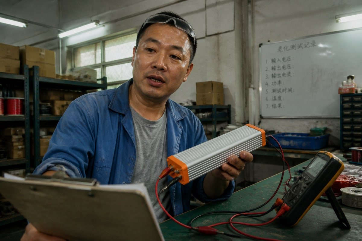
Un e-mail paniqué est arrivé à notre usine le printemps dernier : le compteur d’un client affichait une tension “ erronée ” après l’envoi de commandes DALI. Rien n’était cassé. Ce malentendu fait perdre des heures, alors laissez-moi démêler cela.
Les commandes DALI ne définissent pas une tension de sortie LED spécifique. Elles envoient un niveau numérique de puissance d’arc ou de flux lumineux de 0 à 254. Le driver LED DALI interprète cette commande et régule sa propre tension et son propre courant de sortie pour atteindre la luminosité demandée pour la charge LED connectée.
Cette seule distinction explique la plupart des confusions autour de la gradation DALI. Dans cet article, je vais expliquer ce que les commandes changent réellement, comment vérifier le comportement du driver, pourquoi la tension bouge pendant la gradation, et comment vous pouvez personnaliser la réponse pour votre projet.
Que changent réellement les commandes DALI dans la tension de sortie de mon driver LED ?
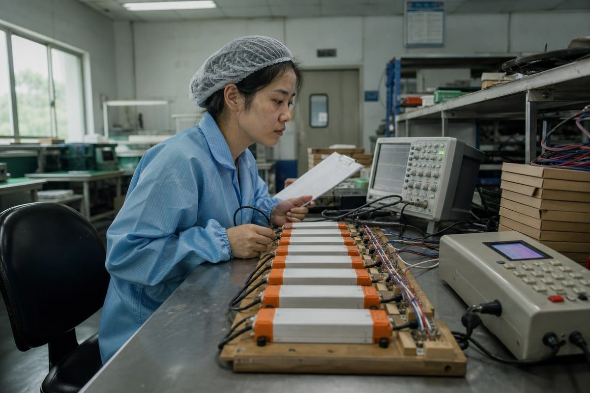
Sur notre banc de test en fin de ligne, chaque driver gradable DALI que nous expédions reçoit un balayage complet de commandes. En observant ces journaux de test quotidiennement, j’ai appris exactement quelles commandes comptent.
Les commandes DALI telles que DAPC (Contrôle Direct de Puissance d’Arc), UP, DOWN, STEP UP et RECALL MAX LEVEL changent le niveau de lumière cible du driver, pas directement sa tension. Le contrôleur ajuste ensuite le courant, la tension ou le rapport cyclique PWM en interne pour atteindre cette cible demandée.
Pensez à la chaîne de contrôle comme ceci : commande DALI → niveau de lumière demandé → boucle de contrôle du driver LED → tension et courant de sortie → émission lumineuse LED. Le driver, pas le bus DALI, décide du point de fonctionnement électrique réel. Selon la norme IEC 62386 1, une commande de Contrôle Direct de Puissance d’Arc transporte une valeur 8 bits. Cette valeur mappe un niveau de gradation de 0 à 254 sur une courbe de gradation logarithmique, qui correspond à la façon dont l’œil humain perçoit la luminosité. Le driver agit alors comme un convertisseur numérique-analogique, traduisant cette étape numérique en un changement physique de sortie.
Trois tensions que les gens confondent
Les lecteurs confondent souvent trois choses complètement différentes. Je les sépare pour chaque nouveau client, car cette confusion est très courante.
| Type de tension | Valeur typique | Ce que c’est réellement |
|---|---|---|
| Tension du bus DALI | Environ 16 VDC | Signal de communication uniquement, limité en courant à 250 mA |
| Tension de sortie du driver | Dépend de la charge LED | Puissance électrique délivrée à la chaîne de LED |
| Niveau de flux lumineux | Échelle numérique de 0 à 254 | Ce que les commandes DALI contrôlent réellement |
Comment le driver traduit les commandes
Pour un driver à courant constant 2, la commande change le courant régulé. La tension de sortie se stabilise alors là où se situe la tension directe de la chaîne de LED. Pour un driver à tension constante, la tension reste fixe, et le driver module généralement le rapport cyclique d’un signal PWM haute fréquence à la place. Les commandes de configuration comme FADE TIME et FADE RATE contrôlent la vitesse de la transition. Ainsi, une seule commande UP peut décaler la sortie progressivement sur plusieurs secondes, pas instantanément.
Comment puis-je vérifier que mon driver DALI répond correctement aux commandes de tension ?
Un distributeur d’éclairage à Singapour m’a un jour envoyé un message WhatsApp, inquiet que nos drivers “ ignoraient ” les commandes. Dix minutes de tests guidés ont montré que son compteur était sur les bornes du bus, pas sur la sortie.
Vérifiez un driver DALI en contrôlant la tension du bus (environ 16 VDC), en envoyant un niveau de gradation connu de 0 à 254, et en mesurant le flux lumineux, pas seulement la tension LED. Utilisez ensuite des commandes de requête, ou le rapport d’énergie D4i sur les drivers DALI-2, pour confirmer que le driver a atteint le niveau demandé.
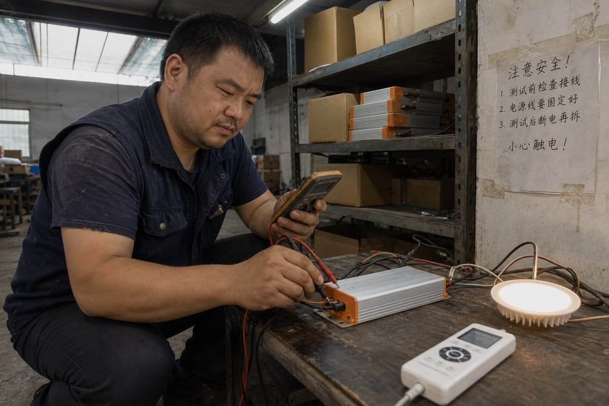
La vérification commence par la couche de communication, pas la charge. Si l’alimentation du bus DALI est faible ou surchargée, les commandes n’arrivent jamais proprement. Le bus est limité en courant à 250 mA ; dépasser cela effondre le signal. Pendant la communication normale, la tension de boucle fluctue d’environ ±2–3 VDC, car les appareils court-circuitent brièvement la boucle pour transmettre des bits. Cette fluctuation est normale, pas un défaut.
Un processus de vérification étape par étape
- Mesurez la tension du bus au repos. Elle devrait se situer près de 16 VDC.
- Envoyez une commande DAPC à un niveau connu, par exemple 128.
- Observez la lumière. Elle devrait bouger en douceur le long de la courbe de gradation logarithmique.
- Interrogez le niveau réel du driver. Il devrait renvoyer la valeur que vous avez envoyée.
- Ce n’est qu’alors que vous mesurez le courant et la tension de sortie LED par rapport à la fiche technique.
Lire le bus correctement
| Lecture du bus | Signification |
|---|---|
| Au-dessus de 9,5 V | Région logique haute ; haut typique près de 16 V |
| En dessous de 6,5 V | Logique basse pendant la transmission des bits |
| 6,5 V à 9,5 V | Zone indéfinie ; des lectures ici suggèrent des problèmes de câblage ou d’alimentation |
Les drivers DALI-2 modernes 3 rendre la vérification encore plus facile. Les drivers D4i conformes à la partie 252 rapportent des données de tension, de puissance et d'énergie en temps réel via des commandes de requête. Dans notre propre processus de contrôle qualité, nous enregistrons ces retours pour chaque lot avant l'exportation, car la certification DALI-2 normalise la manière dont les valeurs de commande correspondent à la sortie chez tous les fabricants. Cette cohérence est exactement ce dont les acheteurs comme les entreprises d'ingénierie ont besoin pour les projets multi-fournisseurs.
Pourquoi ma tension de sortie fluctue-t-elle ou chute-t-elle pendant la gradation DALI ?
Au début de ma carrière dans l'exportation, une équipe de projet en Allemagne a renvoyé un lot qu'elle croyait défectueux. Chaque unité a réussi les nouveaux tests. La leçon est restée : des lectures de tension inattendues signifient généralement une mauvaise interprétation de la physique, pas des drivers défectueux.
La tension de sortie change pendant la gradation DALI car un driver à courant constant réduit le courant des LED, donc la tension directe de la chaîne de LED diminue naturellement. Les fluctuations observées sur un multimètre proviennent souvent de la gradation PWM, des transitions de fondu, ou d'une mesure accidentelle du bus de communication au lieu de la sortie LED.
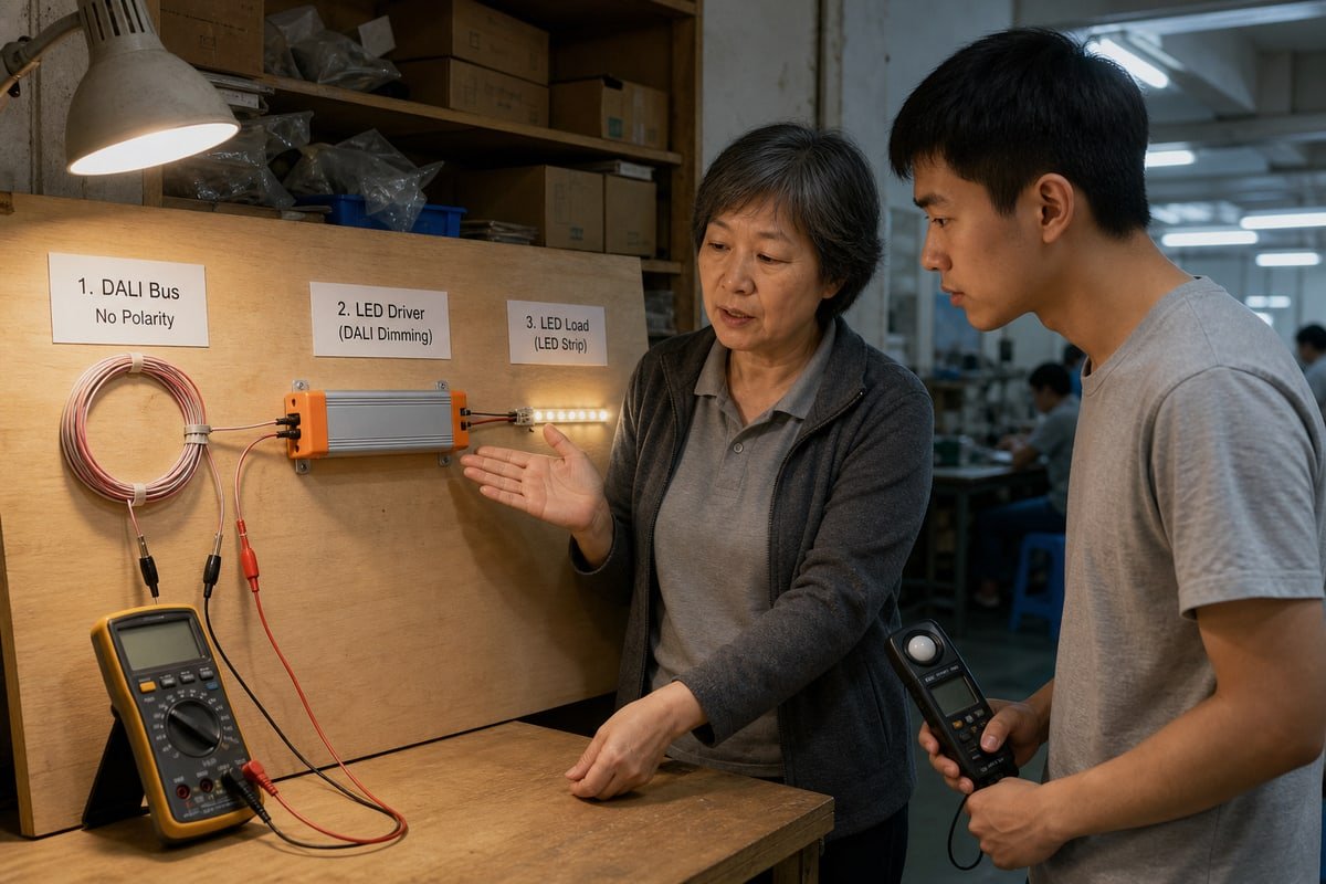
Laissez-moi décomposer cela en cause et effet, car chaque source de “ fluctuation ” a une solution différente. D'abord, la physique de base des diodes. Les LED ont une tension directe qui diminue légèrement lorsque le courant diminue. Ainsi, lorsqu'une commande DALI atténue une driver à courant constant de 100% à 10%, la tension LED mesurée diminue un peu. C'est une régulation correcte, pas un problème de communication. Si un technicien mesure une tension inattendue après avoir changé un niveau DALI, la première question devrait être de savoir si le driver régule correctement la charge LED, pas si DALI a échoué.
Deuxièmement, la gradation PWM. De nombreux drivers à tension constante maintiennent l'amplitude stable et découpent la sortie à haute fréquence. Un multimètre à lecture moyenne affiche alors une “ tension ” qui évolue avec le rapport cyclique. La tension d'alimentation ne s'affaisse pas réellement ; le multimètre fait la moyenne des impulsions.
Causes courantes et leur signification réelle
| Symptôme | Cause probable | Est-ce un défaut ? |
|---|---|---|
| La tension diminue légèrement aux niveaux de gradation faibles | Comportement normal de la tension directe de la chaîne de LED | Non |
| Le multimètre affiche une tension réduite | Sortie PWM moyennée par le multimètre | Non |
| La tension dérive lentement après une commande | Transition FADE TIME ou FADE RATE en cours | Non |
| La tension saute sans nouvelle commande | POWER ON LEVEL ou SYSTEM FAILURE LEVEL déclenché | Vérifier la santé du bus |
| La commande n'a aucun effet visible | Le driver est déjà à la limite MIN LEVEL ou MAX LEVEL | Vérifier la configuration |
Troisièmement, le comportement de fondu. FADE TIME et FADE RATE dictent la vitesse de transition entre les états de sortie. Les drivers avancés utilisent une interpolation interne 16 bits sur la plage de 254 pas, donc les fondus ultra-lents restent fluides sans pas visibles. Pendant ces longs fondus, la sortie dérive naturellement. Enfin, certains drivers à haute efficacité utilisent une mise à l'échelle dynamique de la tension d'alimentation, ajustant la tension du convertisseur DC-DC interne aux niveaux de gradation faibles pour réduire les pertes de commutation et la chaleur. Le mouvement de tension là est une fonctionnalité, pas un défaut.
Puis-je personnaliser la façon dont les commandes DALI contrôlent la tension de sortie pour mon projet ?
Chaque commande personnalisée nous oblige à peser un compromis : verrouiller les paramètres à l'usine donne de la cohérence, tandis que les laisser programmables donne de la flexibilité aux installateurs. Nous recommandons généralement un hybride, et voici pourquoi.
Oui. Vous pouvez personnaliser la façon dont les commandes DALI façonnent la sortie en configurant le niveau minimum, le niveau maximum, le temps de fondu, la vitesse de fondu, le niveau de mise sous tension et le niveau de défaillance système, ou en commandant des drivers avec des courbes de gradation ajustées, une fréquence PWM et des réglages de courant adaptés à votre projet.
La personnalisation se fait à deux niveaux, et comprendre les deux fait économiser de l'argent. Le premier niveau est la configuration DALI standard. Chaque driver conforme stocke des variables qui modifient la manière dont les commandes se traduisent en sortie. MIN LEVEL et MAX LEVEL plafonnent le résultat en interne ; une commande en dessous du minimum atterrit simplement au plancher. POWER ON LEVEL définit la sortie lorsque l'alimentation secteur arrive. SYSTEM FAILURE LEVEL définit le repli si le signal du bus disparaît. Certains drivers passent à pleine sortie à la mise sous tension et chutent à un niveau prédéfini en cas de perte de signal, ce qui signifie que la sortie peut changer même sans nouvelle commande. Pour les hôtels et les hôpitaux, nous préréglons souvent ces valeurs avant l'expédition afin que chaque luminaire se comporte de manière identique dès la sortie de la boîte.
Options de personnalisation au niveau de l'usine
Le deuxième niveau est le réglage matériel et firmware, que nous gérons à l'étape de conception :
- Réglage du courant de sortie. Nous faisons correspondre le point de régulation d'un driver à courant constant à votre module LED exact, afin que le même niveau DALI produise une lumière prévisible sur tout le projet.
- Sélection de la courbe de gradation. La logarithmique convient à la perception humaine ; la linéaire convient aux capteurs de récupération de lumière du jour et aux algorithmes de contrôle.
- Fréquence PWM. Des fréquences plus élevées évitent le scintillement sur les sites riches en caméras comme les studios ou les espaces de vente au détail.
- Performance de gradation profonde. Les drivers avec interpolation 16 bits maintiennent une gradation fluide à 1% pour les cinémas et les salles de conférence.
- Marque et documentation. Nous proposons des logos personnalisables et des designs privés pour les distributeurs construisant leurs propres gammes de produits.
Une exception mérite un avertissement clair. Un convertisseur DALI-vers-0–10V dédié 4 traduit délibérément les commandes DALI en une tension de commande analogique, mappant 0–254 sur une sortie 0–10 V. C'est un dispositif de conversion en aval, pas un comportement normal de driver DALI. Si votre projet mélange des contrôleurs DALI avec des drivers LED gradables 0-10V hérités, utilisez cette interface intentionnellement, et n'attendez jamais qu'un driver DALI standard se comporte de la même manière.
Conclusion
Les commandes DALI demandent des niveaux de lumière ; le driver définit la tension. Mal lire cela coûte du temps et de la confiance aux projets. Choisissez des drivers bien configurés, certifiés DALI-2, et ces surprises disparaissent.
Notes de bas de page
- Site officiel de la norme internationale régissant la technologie DALI. ↩︎
- Source faisant autorité pour les normes et la terminologie du génie électrique liées à l’électronique de puissance. ↩︎
- Alliance industrielle officielle fournissant des certifications et des spécifications techniques pour la technologie DALI-2. ↩︎
- Fournit le contexte sur le protocole DALI et ses différences par rapport aux systèmes de gradation analogiques. ↩︎