Chuyển đến nội dung










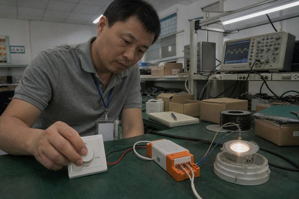
Ghép bộ điều chỉnh độ sáng TRIAC với driver dòng không đổi (CC) trông có vẻ đơn giản cho đến khi dự án nhấp nháy tại công trường. Tôi đã thấy điều này xảy ra với những người mua hàng tin mù quáng vào hai nhãn “có thể điều chỉnh độ sáng”.
Để ghép bộ điều chỉnh độ sáng TRIAC với driver LED dòng không đổi, hãy chọn driver CC được đánh giá cho điều chỉnh độ sáng cắt pha TRIAC, khớp loại cạnh dẫn hoặc cạnh trễ của bộ điều chỉnh độ sáng, điện áp đầu vào AC, dải tải và công suất watt, xác nhận dòng điện và dải điện áp thuận của LED, sau đó xác minh cặp bộ điều chỉnh độ sáng-driver chính xác bằng thử nghiệm thực tế.
Câu trả lời đó nghe có vẻ gọn gàng. Nhưng mỗi mệnh đề trong đó đều ẩn chứa một chế độ lỗi. Dưới đây, tôi sẽ hướng dẫn bạn từng bước kiểm tra, theo thứ tự tôi sử dụng với chính khách hàng của mình.
Tôi nên kiểm tra điều gì trước khi ghép một bộ điều chỉnh độ sáng TRIAC với một bộ điều khiển dòng không đổi (CC Driver)?
Năm ngoái, một kỹ sư thu mua ở Singapore đã gửi cho tôi thông số kỹ thuật của một driver “có thể điều chỉnh độ sáng TRIAC” từ một nhà cung cấp khác và hỏi tại sao đèn downlight của anh ấy lại nhấp nháy ở độ sáng 10%. Bảng dữ liệu không bao giờ cho anh ấy biết điều đó.
Trước khi ghép cặp, hãy kiểm tra mười điều: dải điện áp thuận của LED, dòng điện LED yêu cầu, điện áp và tần số đầu vào của driver, khả năng tương thích cạnh dẫn hoặc cạnh trễ, tải tối thiểu và tối đa, dải điều chỉnh độ sáng, hành vi khởi động, số lượng driver trên mỗi bộ điều chỉnh độ sáng, tải định mức LED của bộ điều chỉnh độ sáng và thử nghiệm tương thích thực tế.

Hiểu biết cốt lõi mà tôi luôn chia sẻ đầu tiên: Khả năng tương thích TRIAC không được xác định chỉ bởi từ “TRIAC”. Vấn đề thực sự là liệu dạng sóng AC bị cắt 1 của bộ điều chỉnh độ sáng có thể được phát hiện và xử lý chính xác bởi tầng đầu vào của driver trong khi vẫn duy trì hoạt động ổn định ở tải yêu cầu hay không. Điều chỉnh độ sáng cắt pha cắt lát sóng sin AC. Driver phải đọc dạng sóng bị cắt đó một cách sạch sẽ, trong mỗi nửa chu kỳ, ở mọi vị trí điều chỉnh độ sáng.
Bắt đầu từ Phía Đầu Ra, Không Phải Phía Đầu Vào
Nhiều người mua bắt đầu với bộ điều chỉnh độ sáng. Tôi bảo họ bắt đầu với tải LED. Driver CC điều chỉnh dòng điện, vì vậy dòng điện đầu ra của driver phải bằng dòng điện định mức của LED, và điện áp thuận của LED phải nằm trong cửa sổ điện áp đầu ra của driver. Nếu ghép cặp đó sai, không bộ điều chỉnh độ sáng nào trên thế giới có thể sửa được.
Sau Đó Chuyển Sang Phía Đầu Vào
Chỉ sau khi đầu ra khớp, tôi mới xem xét phía AC. Đây là danh sách kiểm tra trước khi mua đầy đủ mà tôi đưa cho các nhà phân phối của mình:
| # | Hạng Mục Kiểm Tra | Tại Sao Nó Quan Trọng |
|---|---|---|
| 1 | Dải điện áp thuận của LED | Phải nằm trong cửa sổ đầu ra của driver |
| 2 | Dòng điện LED yêu cầu | Driver CC điều chỉnh dòng điện, không phải điện áp |
| 3 | Điện áp/tần số đầu vào của driver | Sự không khớp 120V vs 230V vs 277V gây điều chỉnh độ sáng thất thường |
| 4 | Cạnh dẫn vs cạnh trễ | Sai loại pha gây ù và ứng suất |
| 5 | Tải tối thiểu và tối đa | Tải dưới mức tối thiểu của TRIAC gây nhấp nháy |
| 6 | Dải điều chỉnh độ sáng | Xác định độ sáng thấp hữu ích |
| 7 | Hành vi khởi động | Khởi động chậm hoặc nhấp nháy gây khó chịu cho người dùng cuối |
| 8 | Số driver trên mỗi bộ điều chỉnh độ sáng | Dòng điện khởi động tích lũy 2 giới hạn số lượng |
| 9 | Tải định mức LED của bộ điều chỉnh độ sáng | Thường thấp hơn nhiều so với định mức đèn sợi đốt |
| 10 | Thử nghiệm tương thích thực tế | Bằng chứng duy nhất rằng cặp hoạt động |
Một cảnh báo tôi đưa cho mọi khách hàng B2B: đừng ghép driver với bộ điều chỉnh độ sáng chỉ dựa trên công suất watt. Tải LED 30 W không có nghĩa là bạn chỉ cần một “driver tương thích TRIAC 30 W.” Công suất watt chỉ là một dòng trong mười dòng.
Làm sao tôi biết driver CC của tôi có tương thích với bộ điều chỉnh độ sáng TRIAC của tôi không?
Khi chúng tôi phát triển một driver TRIAC có thể điều chỉnh độ sáng mới tại nhà máy của mình, chúng tôi thử nghiệm trên bàn với hàng chục mẫu bộ điều chỉnh độ sáng trước khi phát hành. Thói quen đó đến từ một bài học khó khăn: bảng dữ liệu hứa hẹn, dạng sóng chứng minh.
Một driver CC tương thích khi bảng dữ liệu của nó nêu rõ hỗ trợ điều chỉnh độ sáng TRIAC hoặc cắt pha, đầu vào của nó khớp với loại pha và điện áp của bộ điều chỉnh độ sáng, tải được kết nối nằm trong dải định mức LED của bộ điều chỉnh độ sáng, và cặp chính xác xuất hiện trong danh sách tương thích đã được nhà sản xuất kiểm tra hoặc vượt qua thử nghiệm trên bàn.
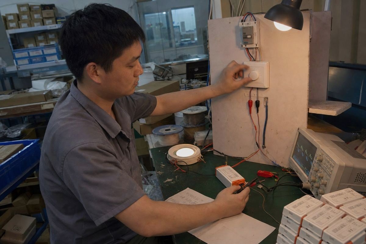
Đây là quy trình xác minh tôi khuyên dùng, theo đúng thứ tự chúng tôi sử dụng trong phòng thí nghiệm của mình.
Quy Trình Xác Minh Năm Bước
- Đọc bảng dữ liệu của driver. Tìm từ ngữ rõ ràng: “TRIAC có thể điều chỉnh độ sáng,” “tương thích cắt pha,” “tương thích cạnh dẫn,” hoặc “pha thuận.” Các thuật ngữ mơ hồ như “có thể điều chỉnh độ sáng” một mình là dấu hiệu cảnh báo.
- Đọc bảng dữ liệu của bộ điều chỉnh độ sáng. Xác nhận nó được ghi “tương thích LED” hoặc “cắt pha đa năng,” và lưu ý tải LED tối thiểu và tối đa của nó, không phải tải đèn sợi đốt.
- Khớp loại pha. Cạnh dẫn đầu so với cạnh kéo sau không phải là một ô đánh dấu. Bộ điều chỉnh TRIAC cạnh dẫn đầu kết hợp với driver được tinh chỉnh cho hành vi cạnh kéo sau (ELV) có thể kêu ù, quá nhiệt và hỏng sớm.
- Kiểm tra danh sách tương thích. Trong sản xuất, tôi tin tưởng danh sách tương thích bộ điều chỉnh do nhà sản xuất thử nghiệm hơn nhiều so với cụm từ “điều chỉnh TRIAC” in trên bảng dữ liệu. Chuỗi tương tác chạy từ bộ điều chỉnh → TRIAC → bộ lọc đầu vào → bộ chỉnh lưu → tụ điện khối → IC điều khiển, và đầu vào được lọc mạnh có thể khiến một driver “tương thích” khác hoạt động kém với một số bộ điều chỉnh nhất định.
- Thử nghiệm một đơn vị trên bàn, sau đó thử nghiệm thực địa một lô nhỏ. Quét toàn bộ dải điều chỉnh từ từ. Theo dõi nhấp nháy, vùng chết, kêu ù và mất tín hiệu gần cuối dải.
Dấu hiệu của một Driver Điều chỉnh TRIAC Thiết kế Tốt
Các driver hiện đại sử dụng nhiều kỹ thuật để duy trì thân thiện với bộ điều chỉnh cắt pha. Ưu tiên driver có mạch xả thông minh, chỉ hút thêm dòng điện ở mức điều chỉnh thấp để giữ TRIAC ổn định trong khi duy trì hệ số công suất cao ở độ sáng tối đa. Giảm chấn tích cực là một dấu hiệu mạnh khác; nó triệt tiêu dao động cộng hưởng gây ra bởi chuyển mạch nhanh của TRIAC, cải thiện hiệu suất không nhấp nháy trong không gian đòi hỏi khắt khe. Trong các dự án Bắc Mỹ, tuân thủ NEMA SSL 7A 3 là một chuẩn hữu ích, vì nó định nghĩa cách bộ điều chỉnh cắt pha và driver LED nên tương tác với nhau. Cũng kiểm tra đường cong điều chỉnh: sự không khớp tuyến tính so với logarit tạo ra “vùng chết,” nơi di chuyển thanh trượt không thay đổi gì trong một phần dải.
Tại sao Bộ điều chỉnh độ sáng TRIAC của tôi bị nhấp nháy hoặc không thể điều chỉnh độ sáng mượt mà với bộ điều khiển dòng không đổi (CC Driver)?
Một nhà phân phối ở Việt Nam từng gọi tôi trong hoảng loạn: một đèn mỗi phòng điều chỉnh tốt, nhưng ba đèn nhấp nháy. Cùng driver, cùng bộ điều chỉnh, hành vi khác nhau. Nguyên nhân là dòng điện, không phải chất lượng.
Nhấp nháy thường xảy ra vì TRIAC không thể duy trì dòng giữ với tải LED công suất thấp, bộ lọc đầu vào của driver làm méo phát hiện góc pha, hoặc dòng khởi động làm nhiễu quá trình kích hoạt. Triệu chứng bao gồm nhấp nháy ở cuối dải, tắt ngẫu nhiên, vùng điều chỉnh chết, kêu ù và mất tín hiệu.
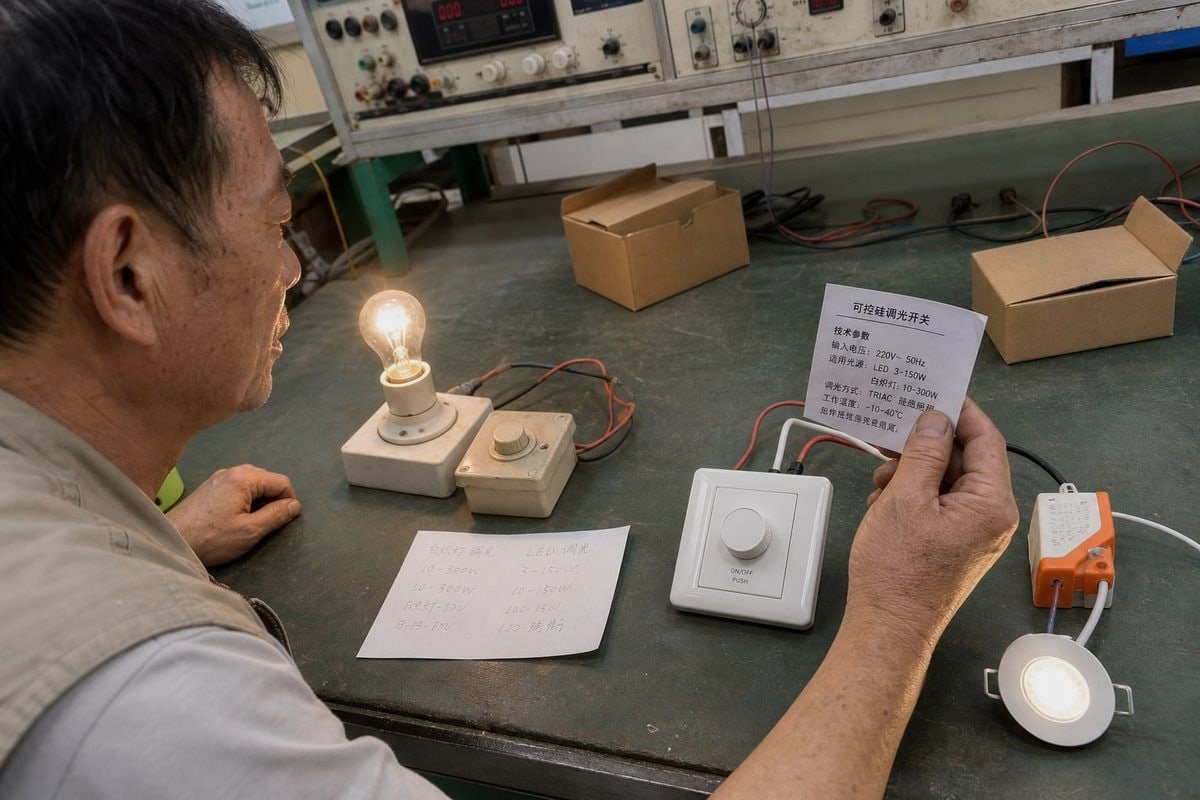
Bộ điều chỉnh TRIAC được thiết kế cho tải điện trở như bóng đèn sợi đốt. Driver LED có đặc tính đầu vào rất khác. Ở công suất thấp, driver có thể không hút đủ dòng điện để giữ TRIAC dẫn ổn định, đặc biệt gần đầu mỗi nửa chu kỳ AC. STMicroelectronics lưu ý TRIAC thường cần khoảng 30–50 mA dòng giữ 4 trong nửa chu kỳ để duy trì khóa. Nếu dòng hút của driver giảm dưới mức đó, TRIAC kích sai, và bạn thấy nhấp nháy hoặc chớp sáng.
Vấn đề Tải Tối thiểu, Giải thích
Đây là vấn đề ẩn mà hầu hết bài viết chung chung bỏ qua. Khi tải quá nhỏ, TRIAC tắt giữa chu kỳ. Driver sau đó mất đầu vào, đặt lại và khởi động lại, lặp đi lặp lại. Đó là hiện tượng nhấp nháy của bạn. Và đây là sắc thái ngành mà nhiều người mua hiểu sai: tăng công suất LED không tự động giải quyết tương thích. Mạch đầu vào của driver, hành vi dòng giữ, chuỗi khởi động, bộ lọc EMI, tụ điện khối và chiến lược phát hiện góc pha đều ảnh hưởng đến cách bộ điều chỉnh hoạt động.
Bảng Xử lý Sự cố Từ Triệu chứng đến Nguyên nhân
| Triệu chứng | Nguyên nhân Khả năng nhất | Khắc phục Thực tế |
|---|---|---|
| Nhấp nháy ở độ sáng thấp | TRIAC mất dòng giữ | Sử dụng driver có mạch xả thông minh |
| Tắt ngẫu nhiên | Tải dưới yêu cầu tải tối thiểu của bộ điều chỉnh | Thêm tải hoặc chuyển sang driver đã thử nghiệm |
| Vùng chết trong hành trình | Không khớp đường cong điều chỉnh | Điều chỉnh trim cuối thấp; khớp đường cong tuyến tính so với log |
| Kêu ù nghe được | Không khớp loại pha hoặc cộng hưởng | Khớp cạnh dẫn đầu/kéo sau; chọn giảm chấn tích cực |
| Hành vi khác với số lượng đèn | Dòng khởi động tích lũy | Giảm tải bộ điều chỉnh; giới hạn driver mỗi mạch |
| Ám sáng khi tắt | Dòng rò qua bộ điều chỉnh | Xác minh tải tối thiểu và thiết kế mạch xả |
Tại sao Số lượng Đèn Thay đổi Mọi thứ
Tụ điện khối của mỗi driver nạp tại thời điểm TRIAC bật. Nhân dòng khởi động đó với mười driver và đỉnh có thể hàn chặt tiếp điểm bộ điều chỉnh, ngay cả khi tổng công suất chạy thấp. Đây là lý do số driver mỗi bộ điều chỉnh nằm trong danh sách kiểm tra của tôi. Cũng điều chỉnh trim cuối thấp của bộ điều chỉnh nếu có; góc dẫn tối thiểu ổn định ngăn driver mất tín hiệu ở cuối dải điều chỉnh.
Bộ kết hợp TRIAC Dimmer và Driver CC nào hoạt động tốt nhất cho dự án của tôi?
Kỹ sư của chúng tôi cân nhắc một sự đánh đổi liên tục khi thiết kế tầng đầu driver: bộ lọc EMI mạnh hơn cải thiện nhiễu điện, nhưng nó có thể làm mờ dạng sóng cắt mà driver cần đọc. Lựa chọn dự án đối mặt cùng sự căng thẳng đó.
Sự kết hợp tốt nhất là bộ điều khiển dòng không đổi (CC driver) từ một dòng sản phẩm có bảng tương thích dimmer được công bố, kết hợp với dimmer TRIAC xoay phù hợp có tải định mức LED bao phủ tổng số driver của bạn với biên độ 10–20%, được xác minh bằng một lần lắp đặt thử nghiệm quy mô nhỏ trước khi triển khai toàn bộ.
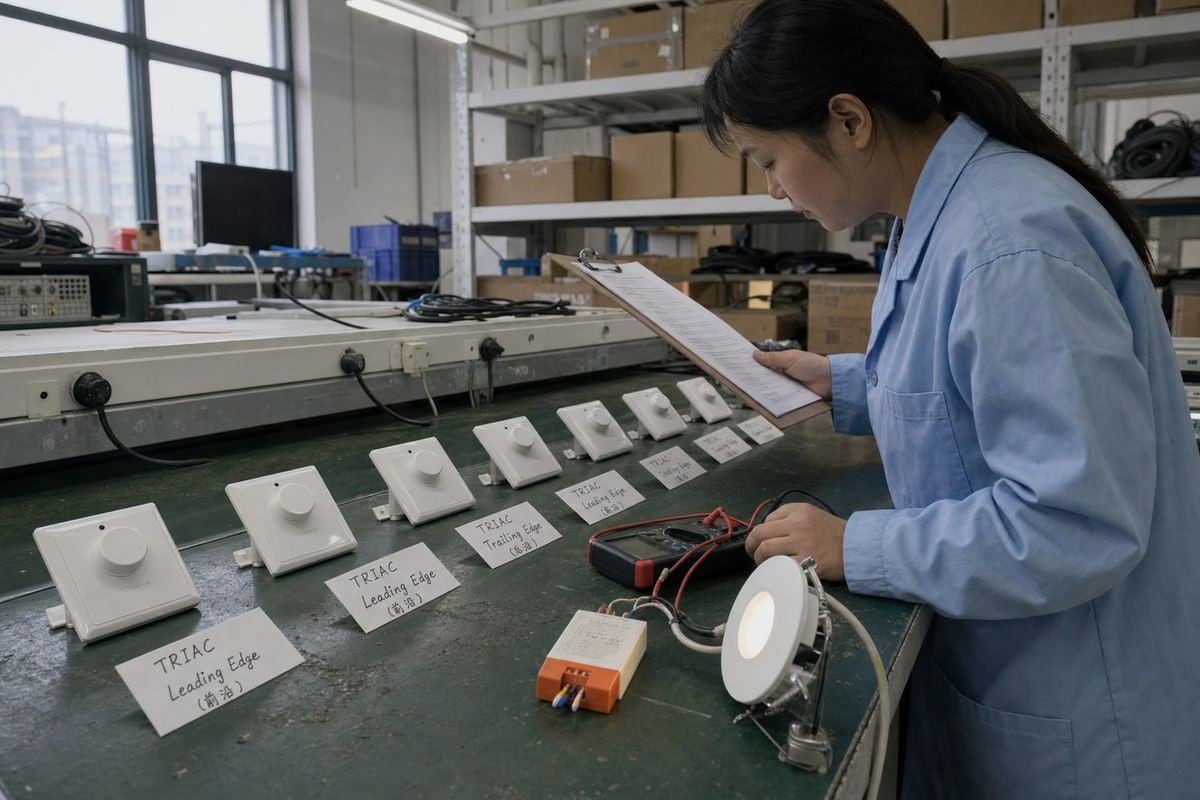
Các dự án khác nhau cần các cặp kết hợp khác nhau. Đây là cách tôi trình bày cho người mua khi họ tìm nguồn cung từ chúng tôi cho công việc kỹ thuật xây dựng trên khắp Đông Nam Á và Châu Âu.
| Loại dự án | Cặp Kết Hợp Được Khuyến Nghị | Thông Số Kỹ Thuật Chính Cần Lưu Ý |
|---|---|---|
| Cải tạo khách sạn, dimmer tường cũ | CC driver cắt pha đa năng | Dải điều chỉnh sáng sâu, ổn định ở mức thấp |
| Đèn downlight dân dụng mới | Dimmer TRIAC xoay + CC driver đã được kiểm tra | Tải định mức LED của dimmer |
| Thương mại nhỏ, ít mạch điện | Dimmer cắt biên sau + driver tương thích | Mượt ở mức thấp, hoạt động êm |
| Thương mại lớn, nhiều mạch điện | Cân nhắc sử dụng 0-10V hoặc DALI thay thế | Khả năng mở rộng và điều khiển tập trung |
Khi Nào TRIAC Là Lựa Chọn Đúng
Một số người mua cho rằng nhãn “có thể điều chỉnh sáng bằng TRIAC” là đủ cho các dự án thông thường. Với một số ít đèn trên một dimmer tường, quan điểm đó thường hiệu quả. Nhưng tôi giữ quan điểm kỹ thuật thận trọng: chỉ có sự tương thích đã được kiểm tra giữa đúng model dimmer và đúng model driver mới đáng tin cậy, vì chi phí cho một lần gọi lại hiện trường lớn hơn nhiều so với chi phí thử nghiệm pilot. TRIAC vẫn là con đường cải tạo hiệu quả về chi phí. Người dùng cuối giữ được bảng điều khiển tường quen thuộc, như dimmer xoay bóng nhỏ gọn có chức năng nhấn bật/tắt mà chúng tôi phân phối rộng rãi, và thợ lắp đặt không cần đi dây điều khiển mới.
Khi Nào Nên Chuyển Sang Giao Thức Khác
Thị trường đang chuyển dịch sang các driver cắt pha đa năng và nhãn tương thích lai, vì khách hàng giữ lại dimmer cũ nhưng mong đợi hiệu suất đạt chuẩn LED. Tuy nhiên, đối với các lắp đặt lớn, 0-10V hoặc DALI bền vững hơn. DALI cung cấp địa chỉ kỹ thuật số 5; nhiều driver sử dụng điều chế độ rộng xung hoặc điều chỉnh sáng lai ở phía đầu ra để đạt mức rất thấp một cách mượt mà. Nếu dự án của bạn có hàng chục mạch điện, các cảnh điều chỉnh sáng dài hoặc yêu cầu nghiêm ngặt về nhấp nháy, thì điều chỉnh sáng cắt pha là công cụ sai. Khi sự tương thích vẫn không chắc chắn sau khi thử nghiệm, việc đổi loại dimmer hoặc dòng driver là giải pháp đáng tin cậy hơn là cố “tinh chỉnh” một cặp không tương thích. Ngoài ra, hãy áp dụng biên độ tải 10–20% trên dimmer như một quy tắc mua hàng và xác nhận các chứng nhận như CE và dấu SELV cho thị trường mục tiêu của bạn.

Phần kết luận
Kết hợp dimmer TRIAC với CC driver bằng các cặp đã được xác minh, không phải bằng nhãn mác. Kiểm tra loại pha, dải tải, dòng giữ và điện áp thuận, sau đó thử nghiệm. Kỷ luật đó ngăn ngừa nhấp nháy và các lần gọi lại tốn kém.
Chú thích
- Giải thích kỹ thuật về cách dimmer cắt dạng sóng AC để kiểm soát công suất. ↩︎
- Định nghĩa kỹ thuật về dòng khởi động ban đầu cao mà các tải điện như LED driver hút vào. ↩︎
- Tiêu chuẩn ngành chính thức để đảm bảo tương thích giữa dimmer cắt pha và LED driver. ↩︎
- Thông số kỹ thuật cho các linh kiện TRIAC và các yêu cầu vận hành của chúng như dòng giữ. ↩︎
- Tài nguyên chính thức cho giao thức DALI, sử dụng địa chỉ kỹ thuật số để điều khiển chiếu sáng. ↩︎